This article covers the build of the YQ2 from cutting the frame parts to assembling the major components. If you have not already seen Part 1 - Design and Part 2 - Materials and Plans, take a look at those articles first.
1. Cutting the GRP / G10 Parts
Print the SketchUp plans at 1-1 scale.
The YQ2 was designed using SketchUp. Download a free copy here.
These plans are free to use for DIY construction. Not for commerial use.
Lower frame 2 off
Upper frame 1 off
Motor mounts 8 off
Camera mount 1 off
Landing gear 4 off
From SketchUp select Camera, Standard Views and then Top.
Zoom the view until the component fills the widow. SketchUp does not have any page dimensions defined, it just prints what is in the window including any dead space around the drawing.
Print (Ctrl P for Windows). At the dialogue box ensure the Fit to page check box is not ticked. In Scale ensure “In the printout” and “In SketchUP” fields both contain 1. This will force SketchUp to print at full scale.
For the lower frame you will either need to print it out using an A3 printer, or you will have to print two parts separately on A4. If printed in two these will have to be joined up when laying out on the fibreglass sheet before cutting.
Once printed measure each paper template to ensure that the dimensions are correct. I have included a reference dimension on each plan, all other dimensions can be checked by using the tape measure tool in SketchUp.
Stick the templates onto the fibreglass or G10 sheet material (I will refer to this as GRP). I use thin double sided tape for this. Where more than one component is required, stick multiple pieces of GRP together with thin double sided tape. The two lower frame pieces can be cut together. For the landing leg brackets and motor mounts, you can cut these four at a time. More than four at once becomes tricky!
Now for the fun part…cut out the frame pieces as accurately as you can. Leaving up to a couple of millimetres on the scrap side is no problem as this will be filed back to the finished dimension.
I have tried a hack saw and a scroll saw to cut GRP, both are very time consuming and hard work. To cut it easily use a ceramic tile saw in a hacksaw frame. This rips though the GRP quite quickly. The dust is an irritant and can be unpleasant to breathe in. Make sure you cut the GRP outdoors in a well-ventilated place. Fortunately the GRP dust is not as nasty as carbon fibre which requires special safety measures when cutting.
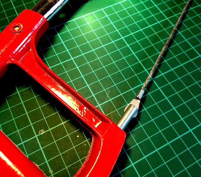
Hack saw with 300mm long ceramic tile blade.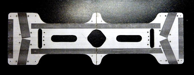
Lower frame parts after cutting. This is a double thickness of GRP with the paper template still in place. All of the bolt holes are drilled before removing the template. NOTE: This part was modified after I built the prototype. The published plans do not include the curved protrusion at the centre, this was removed as a central support for the upper frame was not required.
Once cut with the hack saw, take a 12” flat file with a medium cut. File the GRP back to the finished dimensions on the plans. A round file will come in handy for curved parts. Pilot drill all of the holes shown on the plan with a small drill. I normally use a 1mm drill for this to ensure the location of each hole is accurate. This step is much easier with a Pillar Drill or Drill Press, this also ensures that all the holes are drilled at 90 degrees to the GRP and will come in handy when you drill the holes in the wood parts.
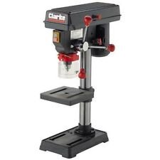
Pillar Drill - The best option for accurate drilling.
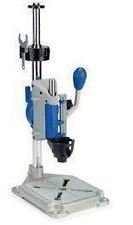
Drill Press - These hold a handheld drill or Dremel tool.
Some holes need to be precisely in the right place, others are not so critical. The important holes are those that locate the motor arms and the 8 holes that locate the red silicone vibration mounts.
Open up each hole to its correct dimension as detailed on the plans.
Some of the holes are not used and are there to give mounting options for additional equipment. Just drill these out at 2mm diameter or whatever size you require. Once this step is complete this is the hard work over. Everything else bolts together with a minimum of effort.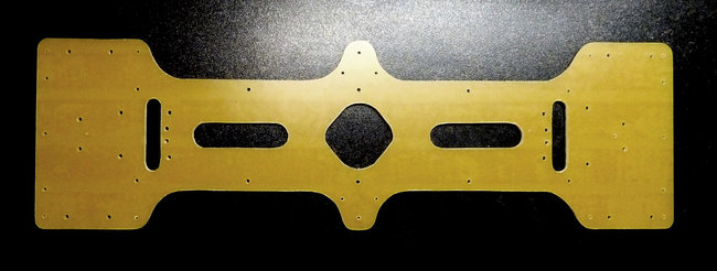
The finished lower frame parts. Soak in soapy water to separate the GRP into two parts.
Separate any GRP parts that were cut together. Wash all parts in soapy water and check them against the plans.
The four central mount holes in four of the motor mounting plates will need countersinking to suit the bolts that came with your motor. IMPORTANT– If you countersink them on the wrong side, the motor wires will not run along the motor arm. Check which is the correct side by offering up a motor to each plate before countersinking. I remade mine twice before realising my mistake!
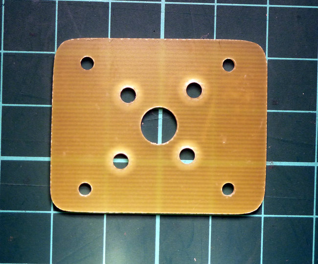
One of the eight motor mount plates. Four of these plates need countersinking to accept the motor screws.
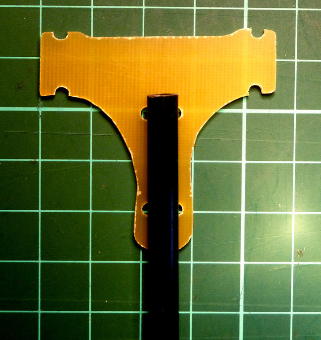
One of the four landing leg brackets with 6mm diameter carbon fibre tube. This is fastened to the frame with 2.5mm wide cable ties. Wooden doweling can be used instead of the carbon fibre.
Cut the wooden motor arms and frame ribs to length and paint them matt black.
2. Assembly
Take the lower two frame parts and match them together as they were when they were cut. Place one of the two long ribs between the two frame pieces and accurately mark the position of one of the end bolt holes. Make sure the rib is accurately lined up in its final position.
Use a Pillar Drill or Drill Press to make a 90 degree hole through the wood. Loosely bolt the rib in place between the frame halves. Check its position and adjust if required.
Line up the rib with the edge of the frame and mark the position of the bolt hole at the other end of the rib. Locate and drill a second hole at the other end of the rib and locate it by loosely fastening a bolt in place. Check it’s position to ensure it is accurately lined up with the frame.
Fasten long rib number 2 and the short 96mm long ribs using the same method. Once all of the ribs are located you can drill out the remaining holes in the wooden ribs by using the GRP frame as a guide.
Remove one of the lower frame halves once all of the holes in the wood have been drilled.
Cut 16 x 10mm lengths of the silicone tube. Place the 3mm bolts (for securing the motor arms) in place with a piece of the silicone tube on each one.
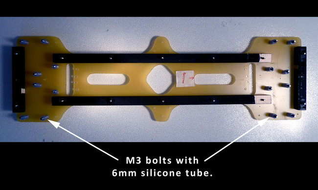
Lower frame plate with wooded ribs and 3mm motor mounting bolts in place. Each motor mount bolt has a 10mm long piece of silicone tube on its thread.
Place the ESCs in the body of the frame. You may have to stagger their positions along the frame to make all 4 fit. I use a piece of double sided copper plated board to connect the power leads together.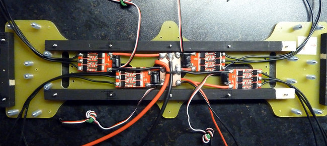
Lower frame with ESCs in position.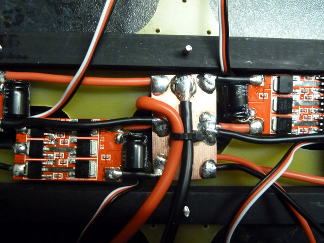
Double sided copper coated circuit board makes a simple and secure connection point for the ESCs, battery and feed for FPV power.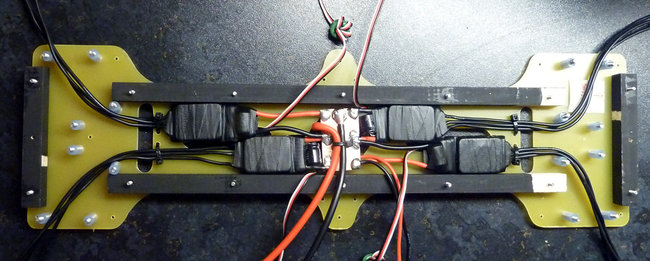
Final location of the ESCs. I use self-amalgamating tape to protect the ESCs. Cable ties at either end of the frame ensure the motor wires do not move around.
Assemble the lower frame and tighten all of the bolts with the exception of the M3 motor arm bolts.
Slide the motor arms into their locating points between the bolts with the silicone tube. Nip up the M3 bolts to secure them in place. These bolts do not need to be very tight.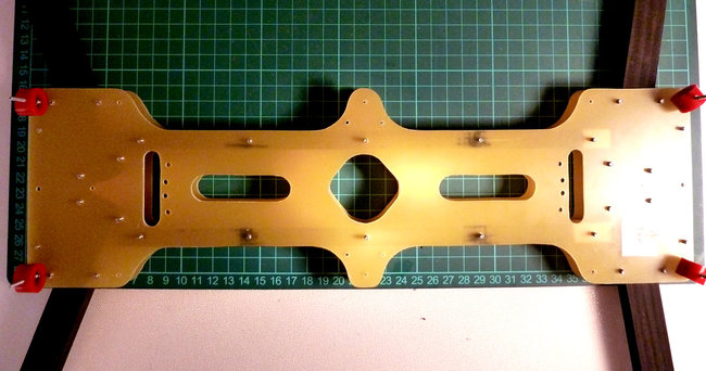
Lower frame plates and motor arms in place (shown without ESCs in the frame).
Battery / Controller and Camera Mount Assembly.
Take the top frame battery / controller board plate and drill appropriate holes for your chosen control board. Holes are already located for a CC3D controller board.
Use the lower frame to locate the 4 mounting hole positions with the top frame. Locate and drill out the mounting holes in the 10mm square wood lengths that hold the top frame together. Not all of the holes are required to secure the wood, 4 in the front section and 8 in the rear are sufficient.
Apply a GoPro self-adhesive flat mount to the camera plate. There are two holes marked on the plan, these holes correspond with the centre of the GoPro mount to assist with alignment.
Apply self-adhesive Velcro to secure the camera plate to the frame. This is secured by using hooks on both the camera plate and top plate with a double sided piece of Velcro loops sandwiched in between.
Mount the motors on the arms and connect to the motors to the ESCs using 3.5mm female bullet connectors. Make sure these wires have quite a bit of slack at the point where they enter the lower frame.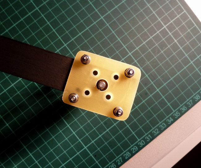
Lower motor mounting plate.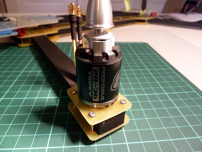
Motor secured in place.

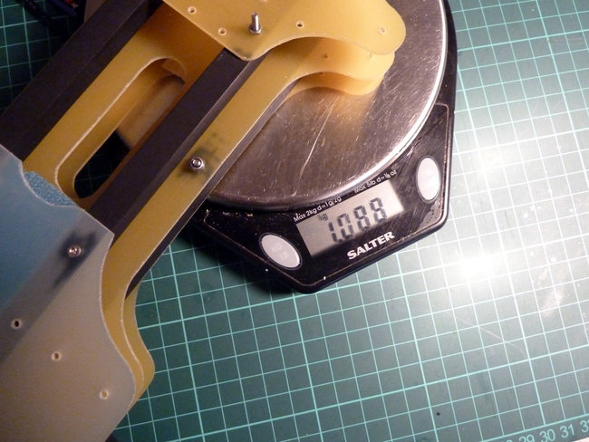
Finished frame weight without motors, ESCs or wiring..
Finished frame weight with motors.
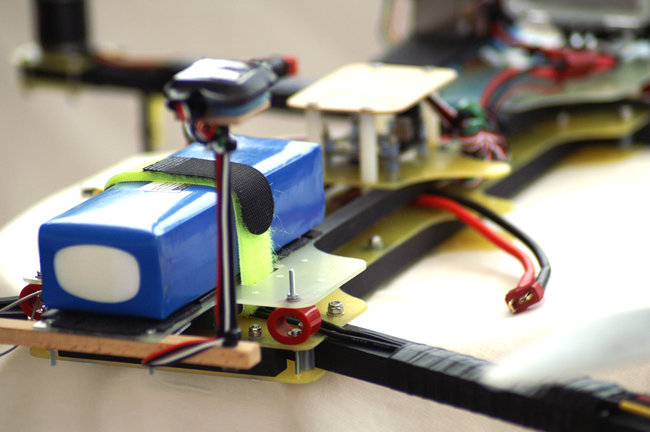
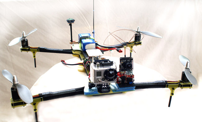
Finished quadcopter with all its electrical systems in place.
This article covers the build of the YQ2 from cutting the frame parts to assembling the major components. If you have not already seen Part 1 - Design and Part 2 - Materials and Plans, take a look at those articles first.
1. Cutting the GRP / G10 Parts
Print the SketchUp plans at 1-1 scale.
The YQ2 was designed using SketchUp. Download a free copy here.
These plans are free to use for DIY construction. Not for commerial use.
Lower frame 2 off
Upper frame 1 off
Motor mounts 8 off
Camera mount 1 off
Landing gear 4 off
From SketchUp select Camera, Standard Views and then Top.
Zoom the view until the component fills the widow. SketchUp does not have any page dimensions defined, it just prints what is in the window including any dead space around the drawing.
Print (Ctrl P for Windows). At the dialogue box ensure the Fit to page check box is not ticked. In Scale ensure “In the printout” and “In SketchUP” fields both contain 1. This will force SketchUp to print at full scale.
For the lower frame you will either need to print it out using an A3 printer, or you will have to print two parts separately on A4. If printed in two these will have to be joined up when laying out on the fibreglass sheet before cutting.
Once printed measure each paper template to ensure that the dimensions are correct. I have included a reference dimension on each plan, all other dimensions can be checked by using the tape measure tool in SketchUp.
Stick the templates onto the fibreglass or G10 sheet material (I will refer to this as GRP). I use thin double sided tape for this. Where more than one component is required, stick multiple pieces of GRP together with thin double sided tape. The two lower frame pieces can be cut together. For the landing leg brackets and motor mounts, you can cut these four at a time. More than four at once becomes tricky!
Now for the fun part…cut out the frame pieces as accurately as you can. Leaving up to a couple of millimetres on the scrap side is no problem as this will be filed back to the finished dimension.
I have tried a hack saw and a scroll saw to cut GRP, both are very time consuming and hard work. To cut it easily use a ceramic tile saw in a hacksaw frame. This rips though the GRP quite quickly. The dust is an irritant and can be unpleasant to breathe in. Make sure you cut the GRP outdoors in a well-ventilated place. Fortunately the GRP dust is not as nasty as carbon fibre which requires special safety measures when cutting.
Hack saw with 300mm long ceramic tile blade.
Lower frame parts after cutting. This is a double thickness of GRP with the paper template still in place. All of the bolt holes are drilled before removing the template. NOTE: This part was modified after I built the prototype. The published plans do not include the curved protrusion at the centre, this was removed as a central support for the upper frame was not required.
Once cut with the hack saw, take a 12” flat file with a medium cut. File the GRP back to the finished dimensions on the plans. A round file will come in handy for curved parts. Pilot drill all of the holes shown on the plan with a small drill. I normally use a 1mm drill for this to ensure the location of each hole is accurate. This step is much easier with a Pillar Drill or Drill Press, this also ensures that all the holes are drilled at 90 degrees to the GRP and will come in handy when you drill the holes in the wood parts.
Pillar Drill - The best option for accurate drilling.
Drill Press - These hold a handheld drill or Dremel tool.
Some holes need to be precisely in the right place, others are not so critical. The important holes are those that locate the motor arms and the 8 holes that locate the red silicone vibration mounts.
Open up each hole to its correct dimension as detailed on the plans.
Some of the holes are not used and are there to give mounting options for additional equipment. Just drill these out at 2mm diameter or whatever size you require. Once this step is complete this is the hard work over. Everything else bolts together with a minimum of effort.
The finished lower frame parts. Soak in soapy water to separate the GRP into two parts.
Separate any GRP parts that were cut together. Wash all parts in soapy water and check them against the plans.
The four central mount holes in four of the motor mounting plates will need countersinking to suit the bolts that came with your motor. IMPORTANT– If you countersink them on the wrong side, the motor wires will not run along the motor arm. Check which is the correct side by offering up a motor to each plate before countersinking. I remade mine twice before realising my mistake!
One of the eight motor mount plates. Four of these plates need countersinking to accept the motor screws.
One of the four landing leg brackets with 6mm diameter carbon fibre tube. This is fastened to the frame with 2.5mm wide cable ties. Wooden doweling can be used instead of the carbon fibre.
Cut the wooden motor arms and frame ribs to length and paint them matt black.
2. Assembly
Take the lower two frame parts and match them together as they were when they were cut. Place one of the two long ribs between the two frame pieces and accurately mark the position of one of the end bolt holes. Make sure the rib is accurately lined up in its final position.
Use a Pillar Drill or Drill Press to make a 90 degree hole through the wood. Loosely bolt the rib in place between the frame halves. Check its position and adjust if required.
Line up the rib with the edge of the frame and mark the position of the bolt hole at the other end of the rib. Locate and drill a second hole at the other end of the rib and locate it by loosely fastening a bolt in place. Check it’s position to ensure it is accurately lined up with the frame.
Fasten long rib number 2 and the short 96mm long ribs using the same method. Once all of the ribs are located you can drill out the remaining holes in the wooden ribs by using the GRP frame as a guide.
Remove one of the lower frame halves once all of the holes in the wood have been drilled.
Cut 16 x 10mm lengths of the silicone tube. Place the 3mm bolts (for securing the motor arms) in place with a piece of the silicone tube on each one.
Lower frame plate with wooded ribs and 3mm motor mounting bolts in place. Each motor mount bolt has a 10mm long piece of silicone tube on its thread.
Place the ESCs in the body of the frame. You may have to stagger their positions along the frame to make all 4 fit. I use a piece of double sided copper plated board to connect the power leads together.
Lower frame with ESCs in position.
Double sided copper coated circuit board makes a simple and secure connection point for the ESCs, battery and feed for FPV power.
Final location of the ESCs. I use self-amalgamating tape to protect the ESCs. Cable ties at either end of the frame ensure the motor wires do not move around.
Assemble the lower frame and tighten all of the bolts with the exception of the M3 motor arm bolts.
Slide the motor arms into their locating points between the bolts with the silicone tube. Nip up the M3 bolts to secure them in place. These bolts do not need to be very tight.
Lower frame plates and motor arms in place (shown without ESCs in the frame).
Battery / Controller and Camera Mount Assembly.
Take the top frame battery / controller board plate and drill appropriate holes for your chosen control board. Holes are already located for a CC3D controller board.
Use the lower frame to locate the 4 mounting hole positions with the top frame. Locate and drill out the mounting holes in the 10mm square wood lengths that hold the top frame together. Not all of the holes are required to secure the wood, 4 in the front section and 8 in the rear are sufficient.
Apply a GoPro self-adhesive flat mount to the camera plate. There are two holes marked on the plan, these holes correspond with the centre of the GoPro mount to assist with alignment.
Apply self-adhesive Velcro to secure the camera plate to the frame. This is secured by using hooks on both the camera plate and top plate with a double sided piece of Velcro loops sandwiched in between.
Mount the motors on the arms and connect to the motors to the ESCs using 3.5mm female bullet connectors. Make sure these wires have quite a bit of slack at the point where they enter the lower frame.
Lower motor mounting plate.
Motor secured in place.
Finished frame weight without motors, ESCs or wiring..
Finished frame weight with motors.
Finished quadcopter with all its electrical systems in place.


And a really detailed build thread in 3 steps. I must admit, i've been waiting for part 3...
You have been a great inspiration for us and me.
So keep up the Work.
Log In to reply
Log In to reply
It's an awsome platform, with so many uses and fun.
I'm about to Mount a ArduPilot mega 2,5 on mine now. It's actually a pity... Since the KK2 now sports an awsome selflevelling by the version 1,5 firmware...
Might build a new one to keep the ol' trusty KK2 airborn.
But you are still a great inspiration. Also to my tricopter.
Log In to reply
Keep up the great work!!!!!!!!!!!
Log In to reply
Log In to reply
Log In to reply
Log In to reply
Log In to reply
Log In to reply
Log In to reply
Log In to reply