Hello Everyone-
This is my first ‘Article’. I have decided to come to the “front room”.
Up until now, alI my Flitetest activity has been out of the sun. . . the forum. . . and thought a much needed awareness was called for those who bypass the dark recesses of the backroom. :)
There’s been one aspect of all multirotors that has nagged me for some time. And that is an insouciant awareness for thrust column efficiency (TCE).
Most builders take little notice of TCE, in that they design and build mostly for a handful of other reasons. Several commercial multirotors designers ignore this aspect as well. Many designers concern themselves with a single or combination of, initial cost, crash repair cost, crash management, size, weight, payload capacity, materials at hand, what they’ve seen before, etc.
Rarely, if ever, is TCE even a consideration.
This is surprising in that some designs can reduce flight time and lift capacity considerably. Most plate-type booms have TCE in the neighborhood of 85%. Many configurations aggravate the TCE by placing the ESC flat, directly in the highest cross-section of thrust. Many place holes in the booms, however that is most likely for weight reduction, and the result is turbulence, buying very little increased lift.
We're now seeing a growing trend of very low TCE in the popularity of the mini-FPV quad. In most cases the ESCs turned flat and out on the booms on those mini's are basically as wide as a 450-650mm quad, but with the much reduced planform thrust area of a 3.5-5" prop. This essentially reduces the TCE to around the upper 70's, or having the “form drag” of the boom at, or close to, 100%. An upcoming project is to take the below techniques and mindset and apply it to this growing niche of multirotors, to provide strength and ease of construction to the small, nimble form factor, possibly providing similar ruggedness and performance with motors of higher KV and smaller prop size.
But before I continue, let's give credit where credit is due. Clean carbon fiber round booms have outstanding TCE. However, I suspect CF tubes are chosen in many cases for weight/strength consideration. Even square wood or aluminum and carbon fiber boom tubes have decent efficiency. Square booms do have a high form drag or high splash, in that the leading edge is flat, but since square tubes or square solid booms have relatively small planform areas, the TCE does not move into a critical region of gross inefficiency overall. I have seen double plates turned vertical, but generally the boom has horizontal structure between the plates, such as screws, standoffs, etc., to improve rigidity. You can spot when there is no TCE awareness, when the ESC is turned flat in planform directly in the most critical area of prop thrust.
So, setting aside those designs which are either horrendous to excellent in TCE, I want to experiment with a paradigm shifting idea. To step beyond even the round clean carbon fiber boom, and get the TCE as close to 100% as is possible, by turning the grossly inefficient common flat boom vertical.
The idea was sparked by my ‘Racing Quad’ design I modeled several months ago. It basically utilized a symmetric camber and shallow airfoil as the booms. It then occurred to me, if the boom could be made stiff enough, a simple flat plate could be used and built much easier and cheaper. So I began to design from that aspect.
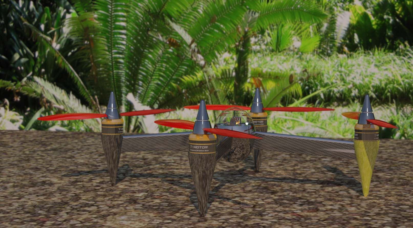
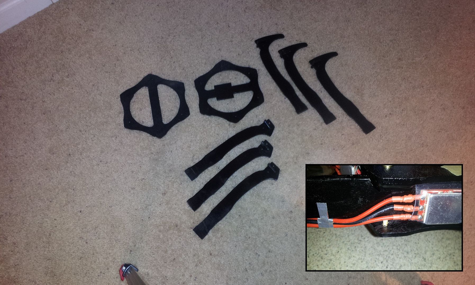
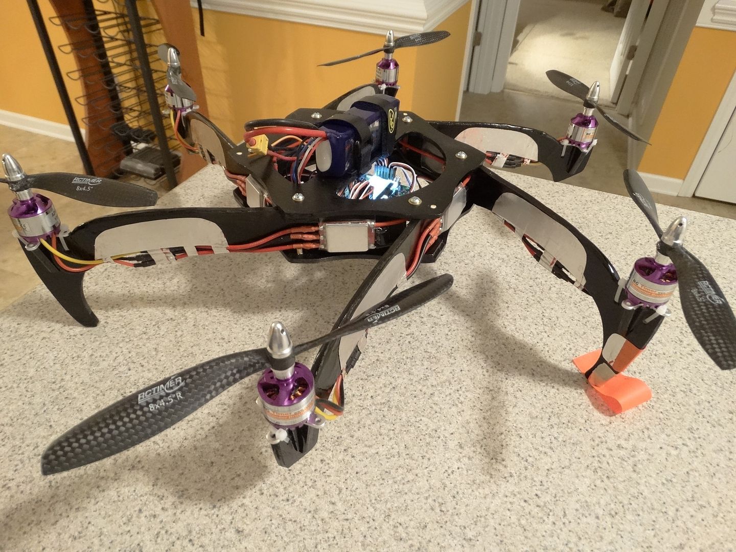
The following hexicopter is made from 3/16” plywood for the booms and 5/32” plywood for the main plates.
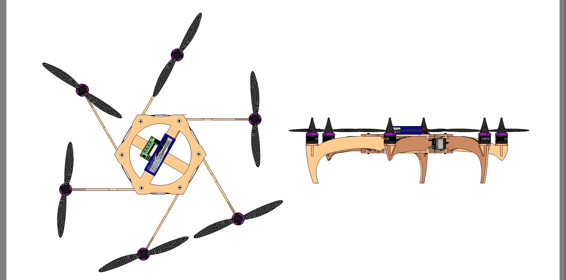
I started by designing my general idea in SketchUp, then tweaked and changed several times until I had a rough structure, then trimmed the main plate and booms down to a size that was not too overly bulky given I was using an average strength material. I then printed out the shapes and spray adhered the image to the plywood and cut them out with a band saw and scroll saw.
I coated the area of most active boom flex with epoxy, essentially adding a ~0.6mm non-reinforced rigid membrane tube. It did indeed increase the rigidity noticeably.
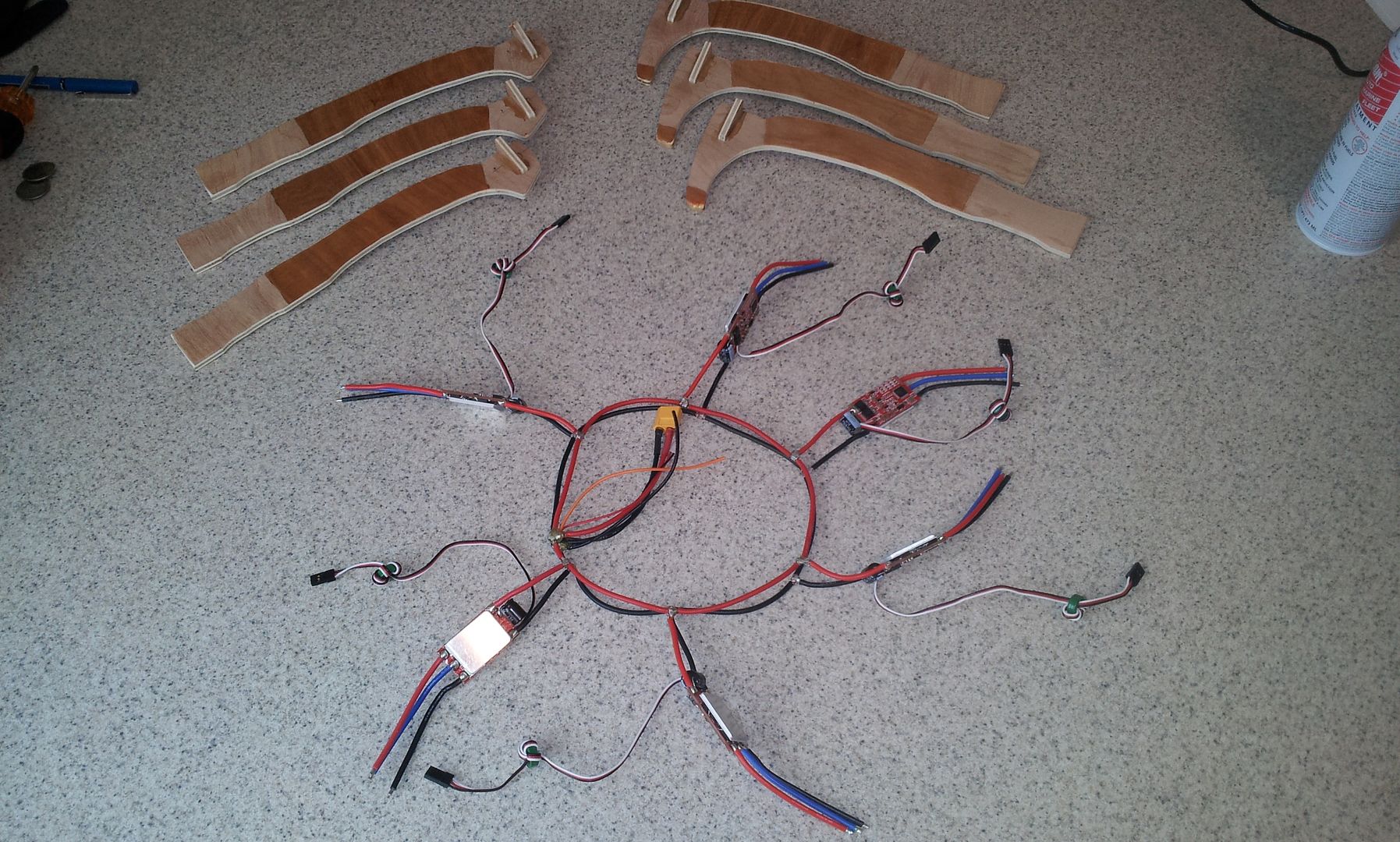
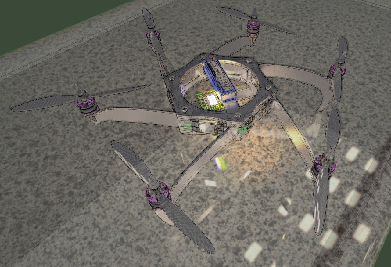
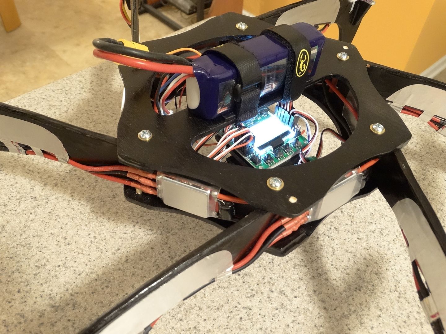
I made a common ring-type harness. All connections are splayed wire T interface connections with a fine copper wire wrapping, then soldered and double coated with epoxy.
I suspect the reason why this design has not been done before, (at least I have yet to see it) is the problematic mounting of the motors on a very thin vertical plate. My solution is straightforward and simple. I used interlocking pieces, wood glued the pieces and reinforced them with two coats of epoxy on the surface. I also did not use the cross piece to zip-tie the motors down. They are only for lateral support, so there is no constant upward pull, or jerk moments on the piece, only compression.
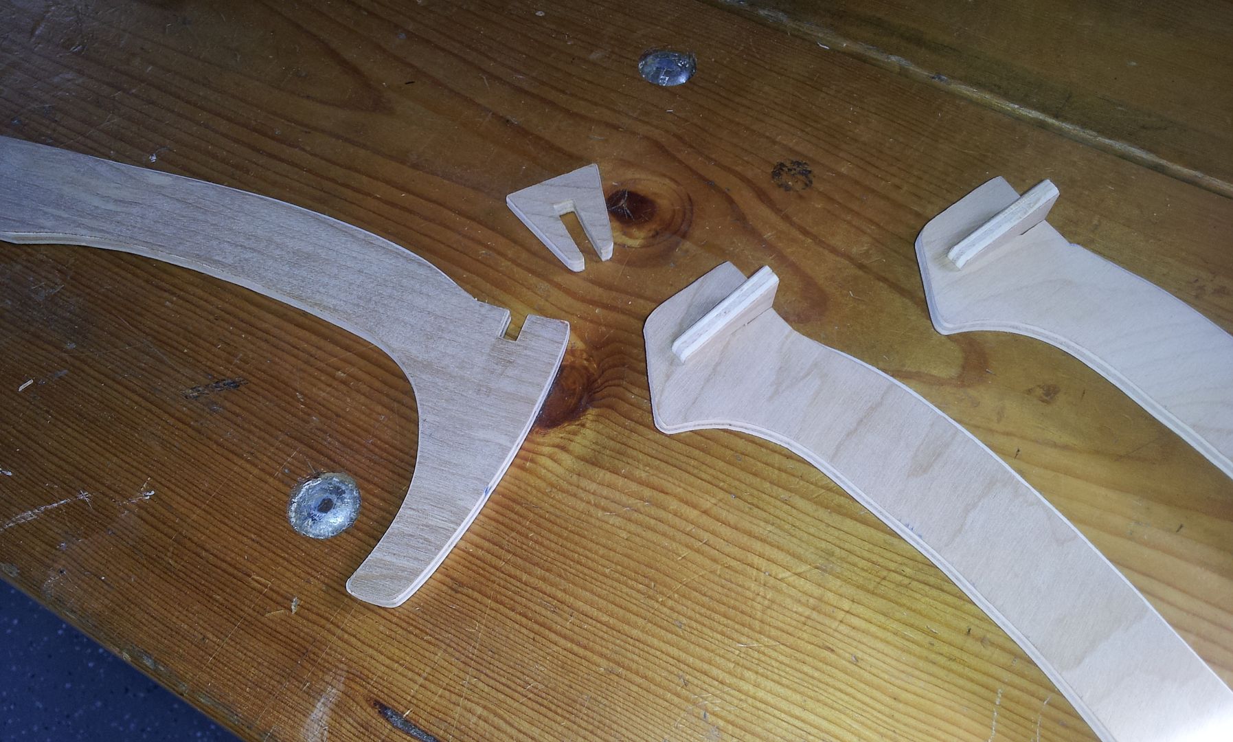
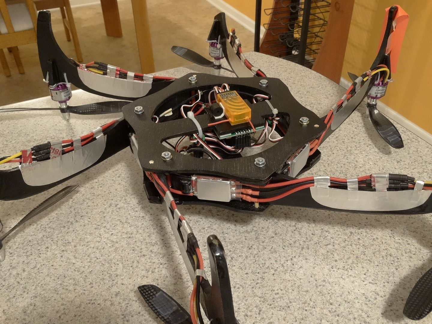
Mounting the vertical booms to the frame is easy. I made blocking tabs and guides at every other corner, and did the same on the opposing plate, offset by a corner, so all corners have blocking and guide rigidity either above or below.
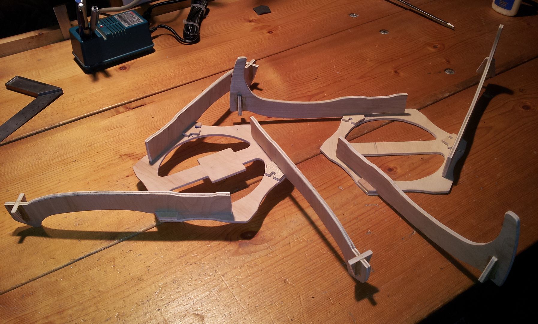
The two halves apart that are pressed together and securely clamped with six screws.
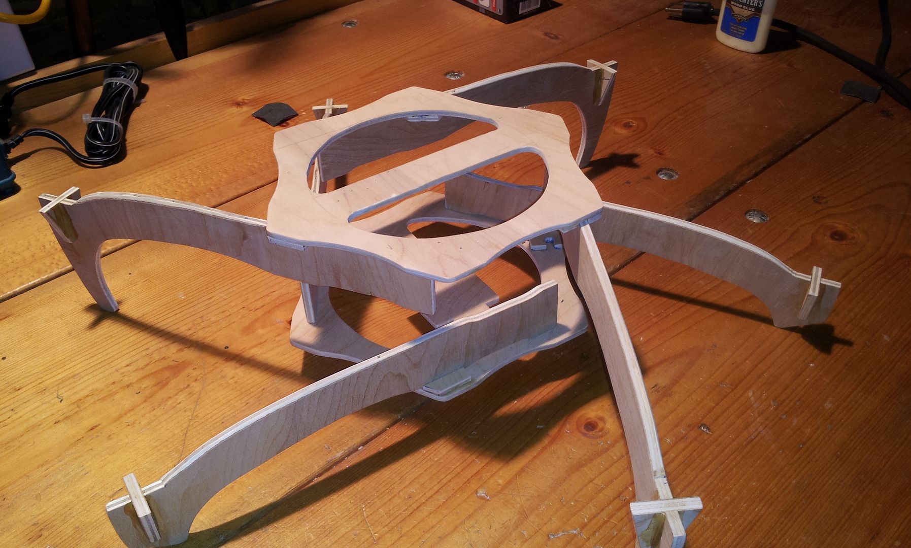
The result is an amazingly strong and rigid six sided box structure that can withstand dozens of kilos of shear, trapezoidal force.
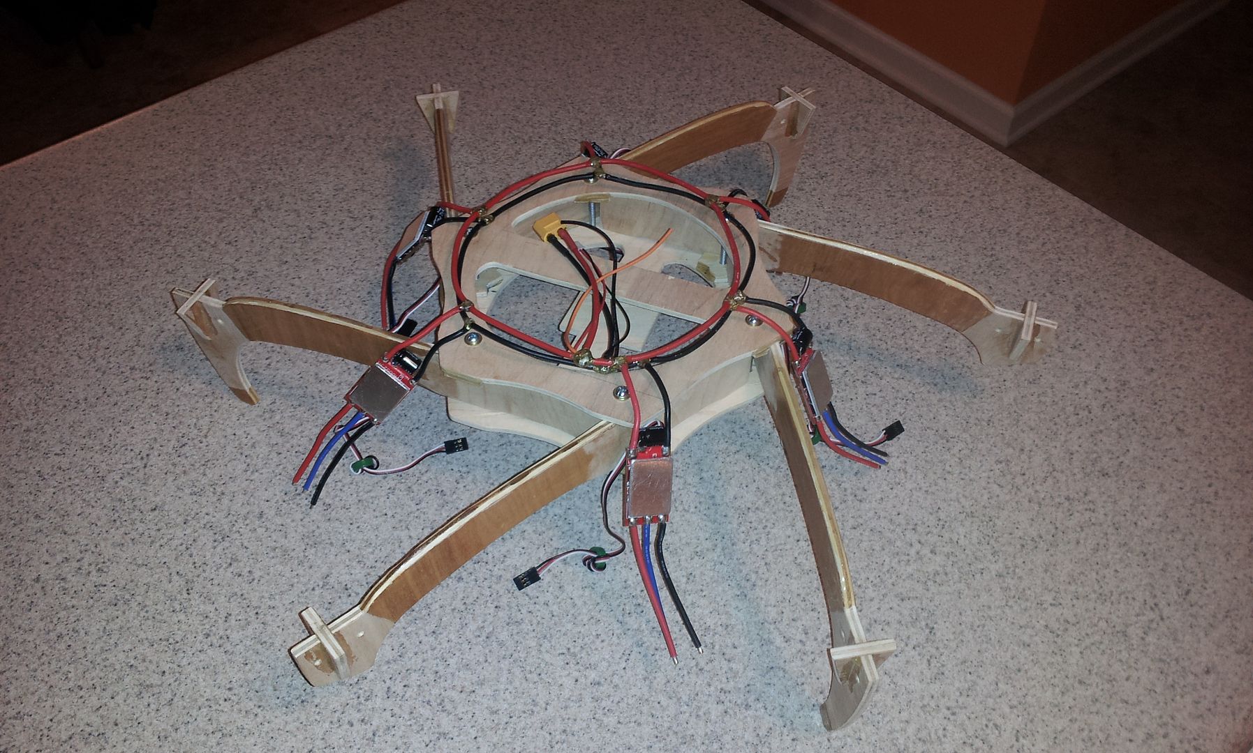
I’m utilizing clear shrink as my ESC mounting material. I’ve indented the booms between the corner points so the shrink does not interfere with the clamp area near each fastener, and to allow higher PSI at the clamp. This also allows the shrink to move freely during the heating process.
I’ve recessed the KK2.1 ‘inside’ the ring for protection and also recessed it back, off center about 20mm, so the Invensense chip is as close to the center of lift and the CG as possible. The battery is mounted on top to put the elevation CG closer in-line with the lift plane. The result is the elevation CG is about 1cm below the lift plane. I mounted the Rx underneath since I used foil tape to affix the motor wires to the booms and did not want to reduce reception by having the Rx and Tx LOS interfered at great distances. Foil tape is extremely strong in uniform tension, but will yield easily in a crash and tear.
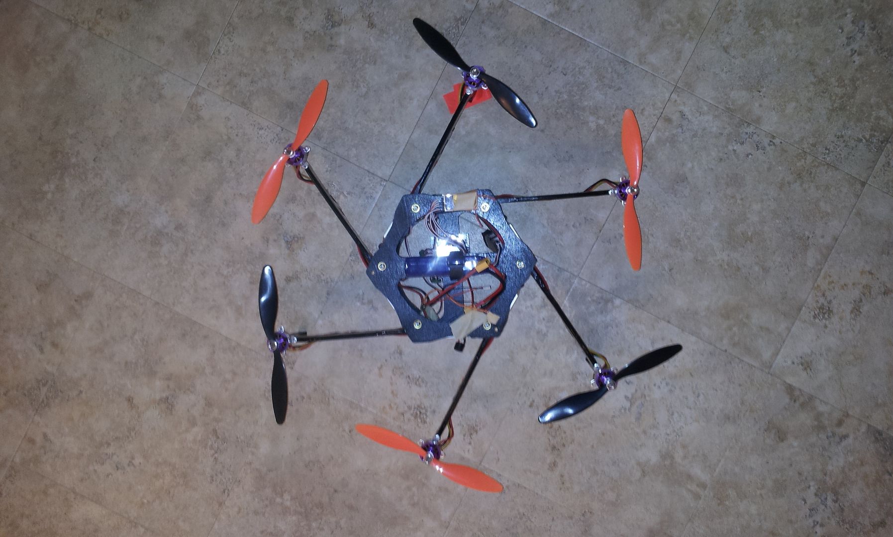
Next came some rattle-can black and putting it together. Both went fast. I was a little worried I would need three hands to wrestle to manipulate it all, but it went together much easier than I thought. Having a block and guide only on one surface at each corner allowed me to slide and rotate each boom into position easily. Another aspect of such a design is I can slightly rotate each boom a degree or so in the plane of the boom for perfect alignment before clamping down hard with the screws.
Last in the build was the organization of the wiring. Most important, this included stacking the motor wires under the 'trailing edge' of the booms. I also rounded the 'leading edge' or top of the boom to reduce the splash obstruction. I've yet to get the wiring 'looking good' along the trailing edge, but that will be done soon.
One post design change I made was adding small wood pins on the outside corner where the boom is merely clamped and not blocked. I added the pins as reassurance against a catastrophic mishap if the clamping screws worked loose. They are not glued, merely pushed tight, so the boom can be unclamped, slid a few millimeters, rotated and removed. Physically removing a broken boom takes a matter of moments after the shrink and ESC is removed.
If this design proves itself, and so far it flies outstandingly well, I may remake it with 2.0mm, 0.3mm and 2.5mm G10. That would drop the frame weight by half, which is currently 415g (with screws). As is, the AUW is just under 1180g with 4S. So I suspect I could get a G10 hex of this approximate configuration, down to an AUW of around 950g with a 4S 2200. I would also fix the booms in place by incorporating the slot and tab technique used in most frame plate and boom designs eliminating the mass of the blocking plates. I almost did use such on this one, but wanted to retain a nice clean upper plate for esthetics, and gluing blocks and guides were easier, faster and required less precision. And of course, making the boom even thinner would shave off another percent or so of thrust column obstruction, increasing the TCE that much more. This plywood frame design is an experiment after all. :)
The final calculation tells me, while this hex has six booms, it has only 20% more planform obstruction in the thrust column as the already excellent thrust column efficient 10x10mm carbon fiber boom tricopter, and only ~75% of form drag or splash obstruction.
And before someone suggests it, yes... I did strongly consider adding a raised mini bulge texture to the boom surface for a micro-turbulant boundary layer. The air velocity is certainly high enough, as well there is enough vertical skin surface area to make it worthwhile.
The technique I considered would have been laying a hex-shaped screen with openings of around 2mm across the flat of the boom, then buttering 15 minute epoxy across the screen. Waiting until the epoxy to set to a rather firm gummy consistency, then gently lifting off the screen. Allowing just enough time to for the resulting hex-shaped 'mounds' of epoxy to flow slightly, round and harden to a nice mound. This uniform texture would improve the TCE by improving the boundary layer off the boom, as well as serve as the stiffener tube. This is something that would require extra effort, or similar could easily be done on the boom material itself during a mass produced manufacturing process.
Because of the substantial increase of G10 strength, if built with G10, it would keep the same motor-to-motor distance, but reduce the frame diameter, as well as the interior diameter would be enlarged, making the plates more like a thin ring. Also the booms would be ~60% thinner and around ~75% the height.
I really need to come up with a more attractive method to stack the wiring. In my upcoming design I will move the bullet connections much closer to the motor to have the connections under the root of the prop where there is almost no thrust.
I am strongly considering building the booms from three plates of G10. Two outer 0.3mm plates sandwiching a main 2.5mm plate. I would then press the wires between the outer plates snug and tight at the bottom trailing edge of the boom. (for a graphic of the cross section, see figure 1). The wires would then be totally hidden and out of the fast moving air.
0.3mm + 0.3mm + 2.5mm x 20mm equaling 3.1mm of G10 would be more than strong and stiff enough for a hex with 175mm booms with 1300Kv motors spinning 0847 props. The TCE would be so high as to be a removed variable in calculating the overall efficiency. I'm looking to have considerably better TCE than a clean round CF tube.
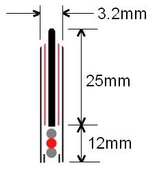
Fig.1
The elecronics are HK F20A ESCs, RcTimer A2830/8 1300KV motors, KK2.1, and an Orange 6ch Rx. I'm using both 3S and 4S 2200s. I ultimately put on RcTimer 0847 carbon fiber props after a half dozen or so flights.
My initial maiden was a crash. But purely because of my confusion. I connected everything up rather late one night and since the ESC power and control wiring 'appeared' to come from the end of the boom's motor, because of the way the booms are inserted, (LOL even though I designed it) I inadvertently hooked them up offset by 60 degrees. It did this weird Euler's Disk thing and the flight lasted about a second.
So. . how does it fly when properly connected? Far better than I imagined! Rock solid and liquid smooth off of Steveis' stock setting of 1.11S2.
Please excuse the crude taping of the stacked motor leads on the trailing edge and the orange orientation tape. As to the slow fly props, I will switch to carbon fiber as my confidence grows flying it. I will also do a much better job of affixing the wires now that I know it flies great. :)


Watching your experiments closely. I was considering a quad build very similar to this as i have concerns about the efficiency around the current designs available. Still use them though. But there is gains to be made for sure. I had the same concerns about lateral flex. Will have to break out the g10 and get to work. I guess the trade off with this design is its fast forward movement drag. No such thing as a free lunch.
Log In to reply
Yes, you're right, drag from the MR's X or Y movement is increased. However, looking at it from a purely F=MA energy loss perspective, in that 100% of the time the booms are subjected to an high velocity down-rush of air, whereas, lateral air velocities are nowhere near as high, and even when moving in a direction at a relatively high speed over the ground, the drag is nowhere near as high in comparison, unless of course the multi-rotor is highly or totally tilted, and then the thin booms are in the best orientation possible. :)
Log In to reply
Log In to reply
I was somewhat worried about flexing of the booms and lateral vibration since prop and motor speed is constantly all over the map, and a harmonic might arise. At this point, my worries have proved unfounded.
Having a aerodynamic central hub is also a strong consideration for the next build, and something I incorporated in my 'racing quad' model, much like your link. But my concentration for this build was simple thrust column efficiency.
Thank you for the comment. :)
Log In to reply
Log In to reply
Indeed. I would adhere the outer 0.3mm plates below the top of the 2.5mm about a mm, so I could easily sand a nice aerodynamic curve to the leading edge as I did to the plywood, reducing the form drag without much work. With the boom being only 3.1mm wide and ~25mm high, I believe I could forgo adding a boundary texture. I'm shooting for a TCE in the upper 90's. With the motor, it's impossible to get to 100%. However, components under the root of the prop cause almost zero obstruction to the thrust column cross section. You can see from my videos the orientation ribbon either does not move, or barely flutters from the thrust. ;)
Log In to reply
I really like your open frame concept, but why not aligning the cross brace to reduce drag further during forward flight?
Finally, i have to tip my hat for going the extra mile in centering the chip and not the FC board. Something else i should have thought of.
Thanks and great work!
Log In to reply
Log In to reply
My confidence level a vertical plate boom not only works, but works outstandingly well is now at a point I can build with a much more pricy material. :)
Log In to reply
Seems like an excellent design for static fpv though, I look forward to the next iteration.
If you were concerned that the arms flex, did you consider tying the ends of the arms together with wire?
Log In to reply