
This project was started as a part of the Flite Test Forum Build-Off: 2015-2016 edition. At first it was intended to be a FPV platform because it has an inline pusher motor.
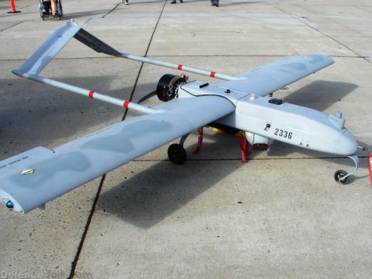
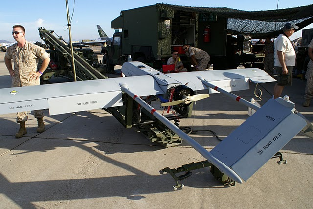
The full-size RQ-7 Shadow is an unmanned aerial vehicle (UAV) with a high-wing, constant chord pusher configuration with a twin-tail boom empennage and an inverted v-tail elerudder. The full-size aircraft is powered by a 38 bhp Wankel (rotary) engine and has fixed tricycle landing gear. It is launched with a pneumatic catapult and it is recovered with the aid of arresting wire and a hook very similar to aircraft on an aircraft carrier.
Full-size RQ-7 Stats
General characteristics
- Length: 11.2 ft (3.4 m)
- Wingspan: 14 ft (4.3 m)
- Height: 3.3 ft (1.0 m)
- Empty weight: 186 lb (84 kg)
- Gross weight: 375 lb (170 kg)
- Powerplant: 1 × Wankel UAV Engine 741, 38 hp (28 kW)
Performance
- Maximum speed: 127 mph; 204 km/h (110 kn)
- Cruising speed: 81 mph; 130 km/h (70 kn)
- Range: 68 mi (59 nmi; 109 km)
- Endurance: 6 h / 9 h Increased Endurance
- Service ceiling: 15,000 ft (4,572 m) ELOS (Electronic Line Of Sight)
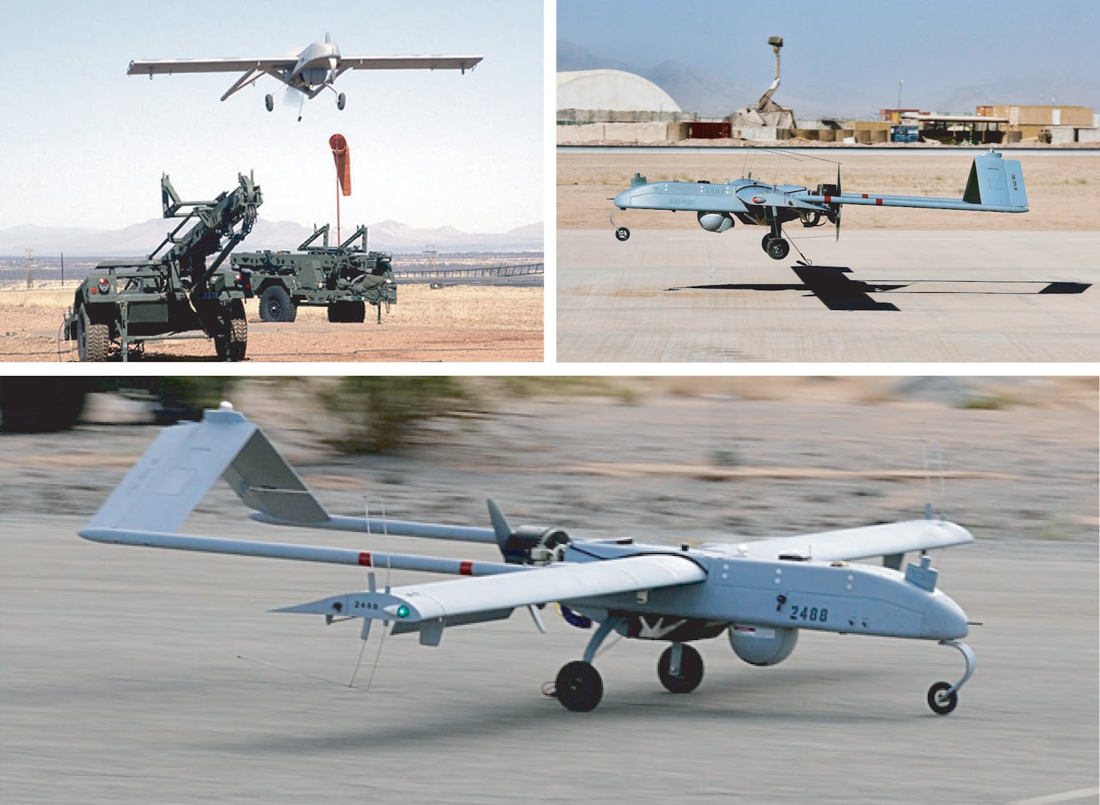
When researching different twin boom tail configurations, I got really excited about the inverted “V” tail. Through my reading I learned that one of the benefits was the angle of the tail control surfaces produced a obligatory coordinated turn since the yaw, roll and pitch were all linked through the control surfaces on the tail. In my searches for inverted “V” tail construction, I ran across the real deal, the RQ-7 Shadow. The twin boom configuration allows the motor thrust to be placed directly behind the main wing and in front of the tail controls surfaces. There was only one problem - I searched the internet again and again for plans, but didn’t find any. Even coming up with 2D drawings was hard, however, through my intensive searches I was able locate a few profile photos of the RQ-7 Shadow as well as a couple profile drawings - I think they were from plastic models packaging.
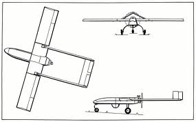
From these I created plans and then scaled them to the photos (based on the wingspan). All parts were outlined and other control surfaces were marked out.

The first prototype was small hand-launch glider that did not have mechanized control surfaces. It worked well and even with static control surfaces, flew (glided) quite nicely. The powered version was created from the plans scaled up to give a 100cm wingspan. The 100cm wingspan (right around ¼ scale, 0.232) was deliberately planned to conveniently be double the width the width of foam core.
Build Difficulty - Intermediate
I would characterise the build difficulty of the RQ-7 to be intermediate because the use of non-standard items used by FT plans like carbon fiber tubes, balsa wood support, plywood motor mount etc. However, the build of the constant chord wing and fuselage are really super easy.
Versions
While completing this build I created 3 versions. They are all very similar, but in these build instructions I provide details for version 3 since it is final. At the end of the article there is a list what was upgraded between the versions.
Conservation of Plans
When you print out the RQ-7 Shadow plans, you will notice that there is only one pattern for each piece. For pieces where two mirror image pieces are needed, like the wing, the second or mirrored piece is created from the same plan, but the plans are flipped over and the marks transferred to the foam board.
As mentioned above, building the RQ-7 Shadow will require you to use a couple of non-FliteTest techniques. For example, the holes in the wing used for mounting the fuselage, boom construction and servos mountings are cut into the wing after the wing is formed. the position of cuts are transferred to the outside surface of the wing by poking holes all the way through the foam board. Here are the steps with details and photos to follow.
Building the Wing
Let’s start with the wing. The wing is created following the standard FT technique. Mark the foam board with marks for cuts, folds and placement lines. Cut out the wing.

Like most FliteTest wings, this design will also use a bevel cut for the leading edge and crease and fold technique for the curved upper panel. Score cut, or crease, along each of the wing airfoil bend lines.
Cut out the wing spar.

The way I do this is to score cut a piece of foam core to make a hinge. Fold it back onto itself, place another piece of foam core next to it to support the straight edge and then cut through both layers of foam board keeping the knife perpendicular to the table.

The resulting spar is even along both edges and easy to glue since the pieces are attached. Glue the spar pieces together.
Glue the spar onto the bottom surface of wing.
Unlike FT, I do not use slots and tabs to align the spar on the wing. I prefer using lines as guides and laying the spar in place.
I use masking tape to hold the spar on the line while it is glued. Lay the spar along the placement line and tape one side to the wing.
Rotate the spar off of the wing surface using the tape as a hinge. Apply hot glue or other and

roll back into place and hold or weigh down. Afterward, the tape can be removed. I found this technique to be easier than trying to design and cut another set of holes in the wing… and it makes a “cleaner” outside wing surface.
Score cut the aileron hinge and bevel cut the hinge. This can be done now or later. I found working with an “open” wing is easier to bevel.
Shaping the Wings
This is done in the normal FT style.

Create the airfoil shape by folding the top wing surface over the bottom wing surface using the double bevel as the hinge point and the spar as the stop. Ensure that the angle of the bends along the entire length of the wing are the same.

Once the initial bends are made, bend the bottom wing surface over the top wings surface so that you can see exactly where the bottom wing surface meets the top wing surface. Make sure the trailing edge of the bottom wing surface lies parallel to the trailing edge of the top wing surface - mine ended up being about 5 mm from the trailing edge hinge line.
Glue wing shape (leading edge, spar and trailing edge).
If I used a score cut for the bends, I hot glue each of the score cuts individually, one at a time, starting with the one on the bottom wing panel and working on the top wing panel from leading edge to trailing edge. Run the hot glue gun down one score cut with the tip delivering hot glue into the cut (hot glue gun being perpendicular to the score cut). This step can be omitted if you’ve chosen to crease along the bend lines.
Once all the score cuts are glued to hold their shape, the double beveled leading edge, spar and trailing edge are all glued at the same time. For this step, I definitely recommend using a hair dryer to warm up the parts so the glue stays pliable for a longer period of time.
Joining the wing halves
The two wing halves are joined with hot glue, but to add strength and to help with the placement, I use a popsicle stick.

Cut a popsicle stick in half and glue one half to the front of of the spar on one wing and glue the other half to the rear side of the other wing’s spar.
The wing halves can be joined by applying hot glue (or Gorilla Glue) to the sticks and the edges of the wing. Hold the wing halves together ensuring the trailing edge and top surfaces match. When I use Gorilla glue, I just tape the wings together after applying the glue.
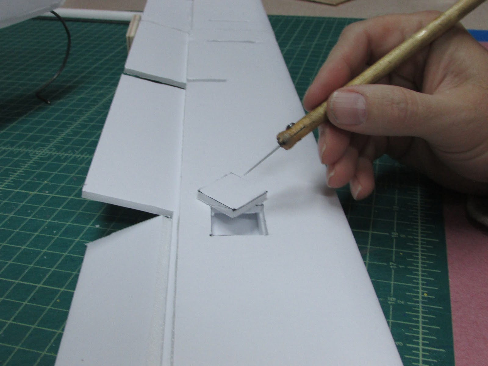
Cut slots in the wing for the fuselage and boom placement.

Using the holes that were punched through to the outside surface as a guide, cut between the holes. I draw a pencil line between the holes so the cutting can be done free hand. Care should be taken not to cut too deeply when cutting holes in the wing. Deep cuts may damage the spar and top surface of the wing. Tear out the foam and paper that you cut out.
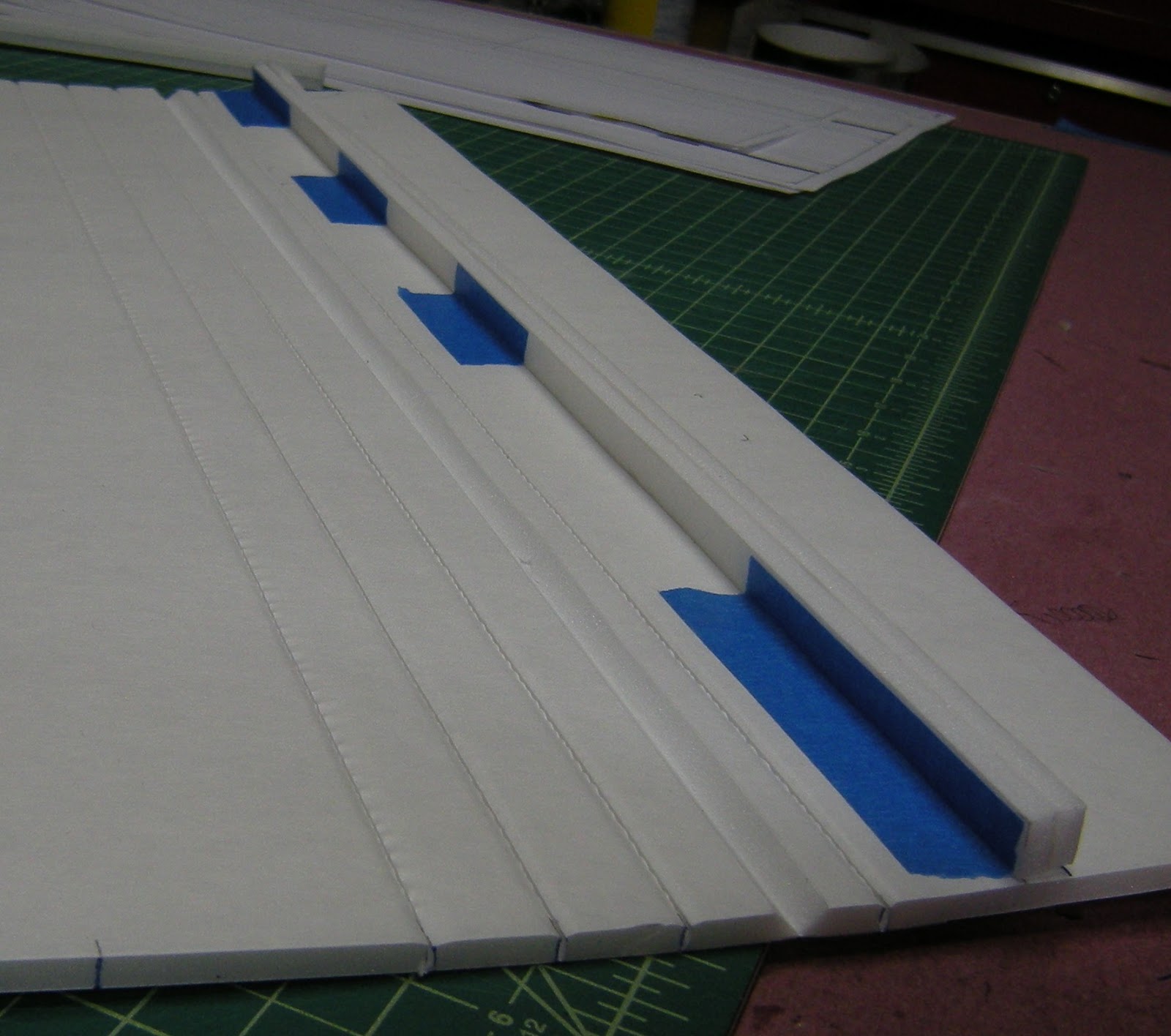
Making the booms
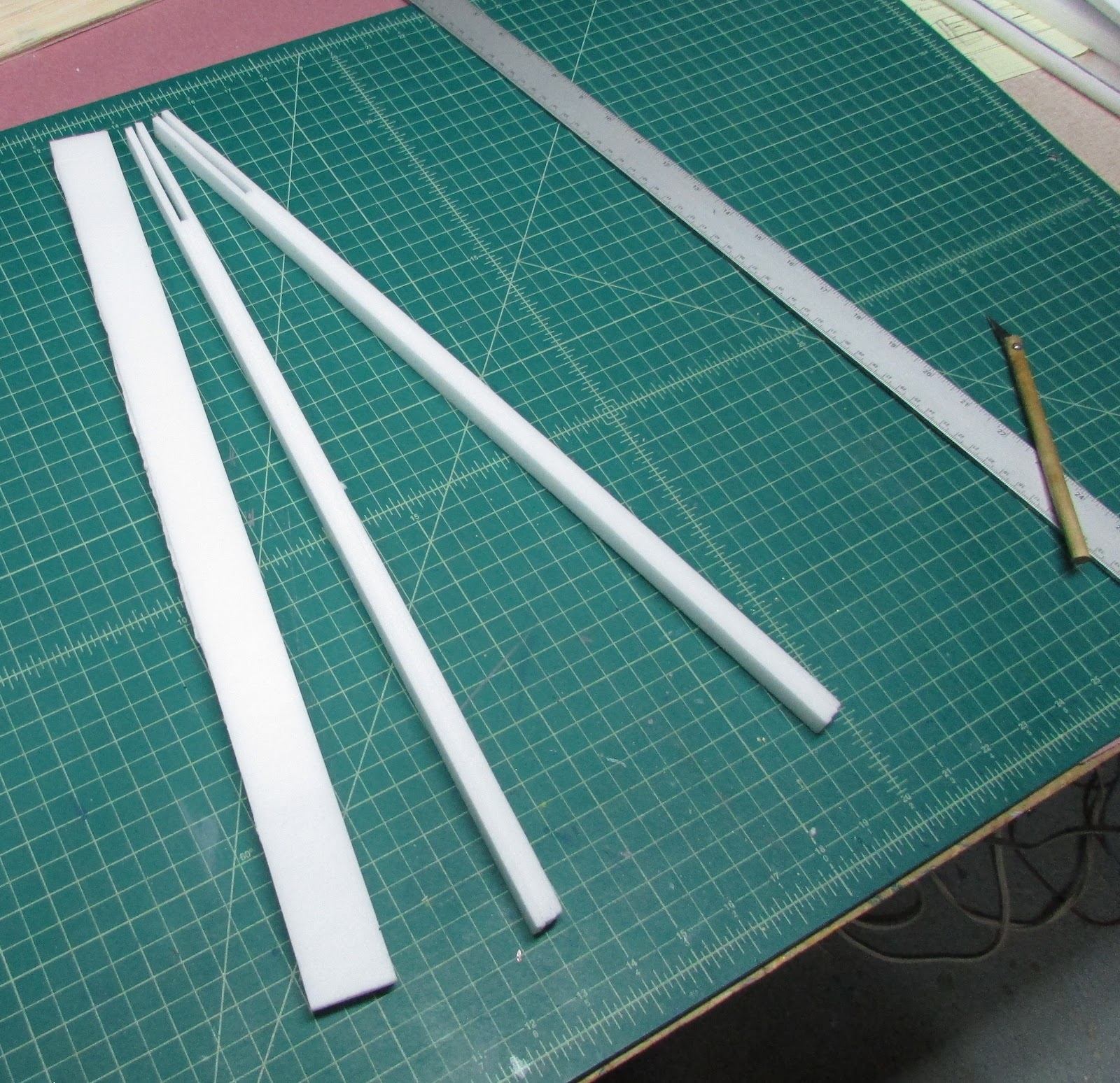
The booms are constructed with 3 ply foam. You can choose to remove the paper or leave it on. I prefer to remove the paper. Cut two sheets 5cm x 50.5cm long and another 5cm wide by 42cm long. In the photos, I made the panels 10 cm wide in case I needed to remake the booms.
Glue these panels together with your favorite glue for large surfaces, I peel the paper from the foam and use Gorilla Glue, spread it with a playing card. I understand that indoor latex primer works really well at gluing sheets together, but I have not yet tried it myself.

I put weight on it to hold the panels together while the glue is curing.
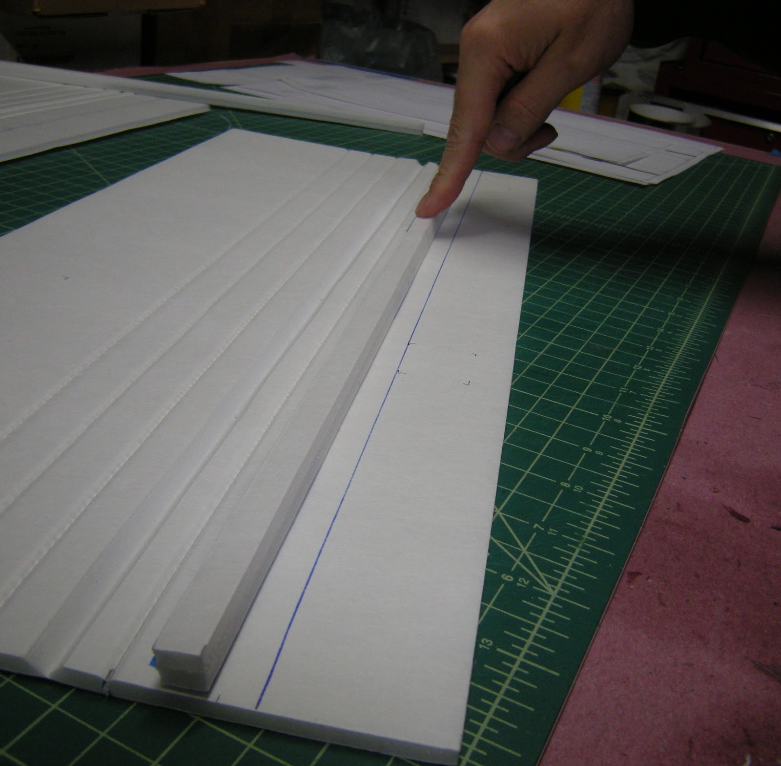
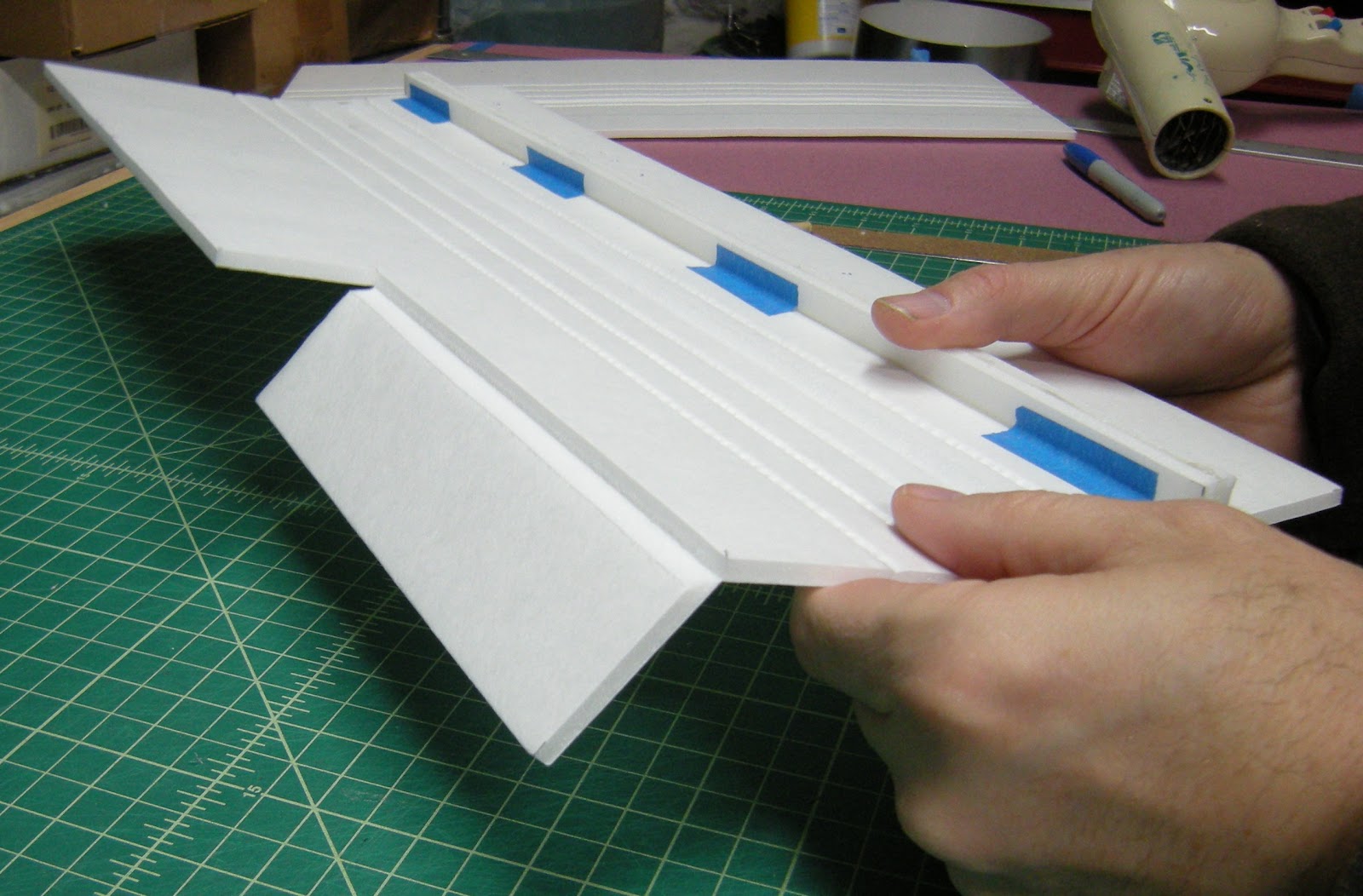
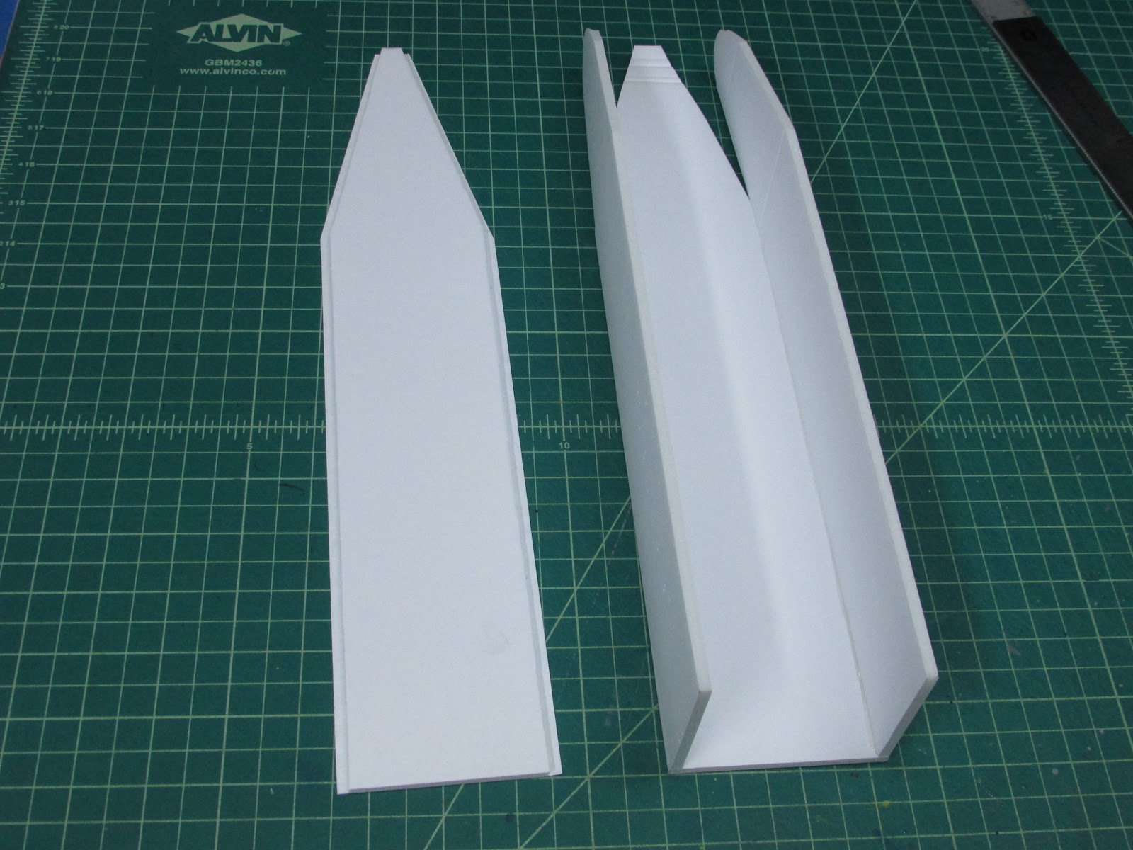
Trim 5mm (or less) off one edge to get a clean edge and then cut two strips that are 1.4cm wide. The 3 ply foam is not strong enough to support the tail without reinforcement so I use two carbon fiber tubes to help support the boom. Lay the 3 ply foam on edge and gouge out a 3mm rough along the middle piece of foam. I use a DIY hot wire cutting tool to cut a trough, but it can also be done by introducing a small score cut into the foam a few millimeters deep and expand the cut by running a piece of carbon fiber inside the cut to smoosh the edges.

On one side of the boom, which will become the upper inside, glue a 2mm or 3mm carbon fiber tube that is 37.3cm long into the trough aligning the rear of the carbon fiber with the rear of the center foam panel (right photo, bottom boom). This carbon fiber tube will become the control rod conduite, that is why it does not extend all the way to the front of the boom (left photo, bottom boom). Glue another 2mm or 3mm carbon fiber tube or rod that is 50 cm long onto the other side. This rod will extend from the front to the back. It will extend along open space where the middle foam panel stops (right photo top boom).

When the tail is glued on, the exposed carbon rod will support the tail. The foam along the bottom edge of the tail is troughed out to accept the carbon tube as shown above.

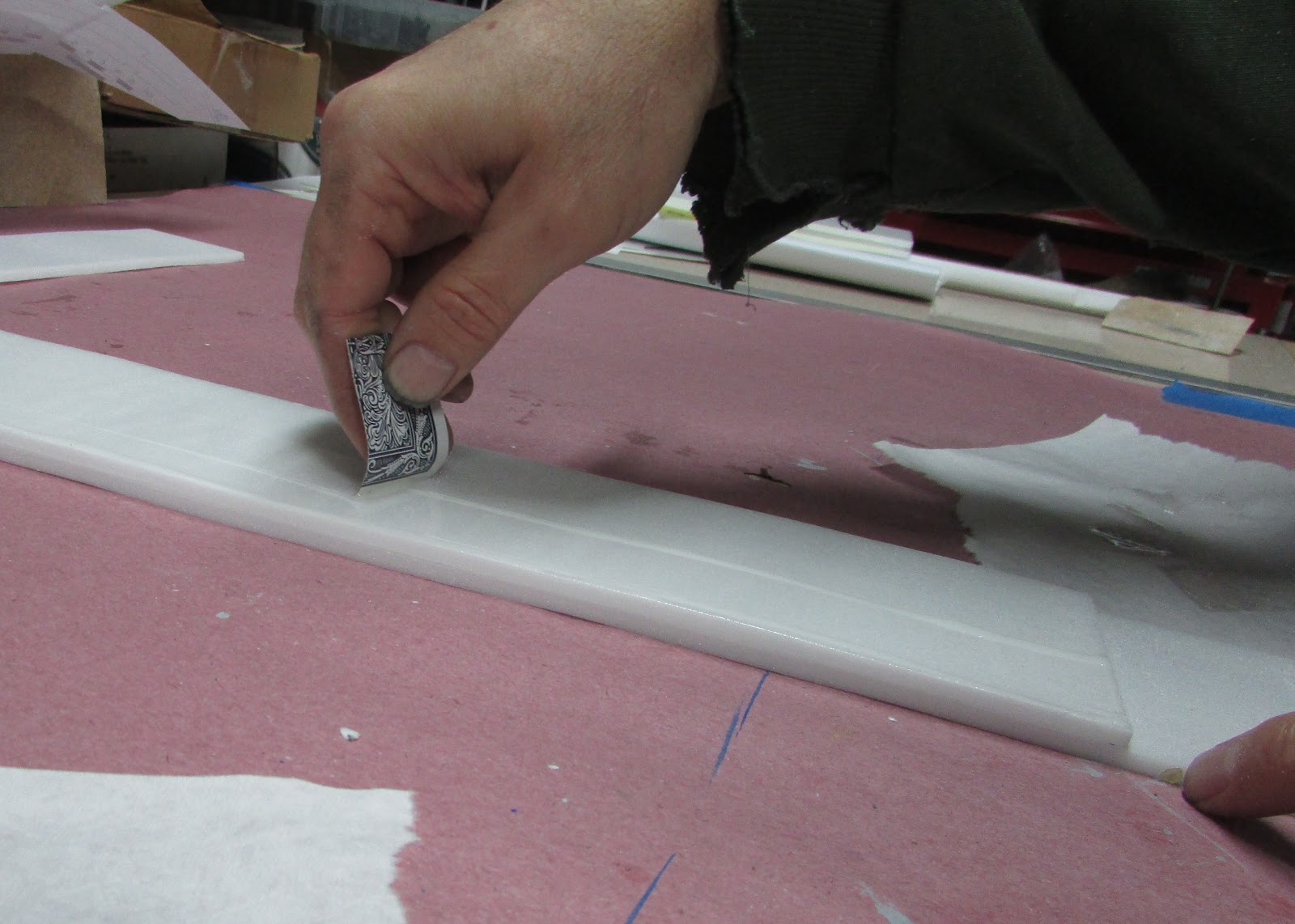
To glue the carbon fiber tubes into the boom, I run a small bead of Gorilla glue along the trough and run a scrap piece of carbon fiber along the trough to spread the glue. Lay the carbon fiber tube into the trough and press into place. Tape over it with masking tape to prevent the glue from pushing the carbon fiber out of the trough. Lay on a flat surface and add weight to hold it straight and keep the carbon tubes in place while the glue cures. Alternatively, epoxy or any number of other glues could be used. I prefer to wait for the glue to get really tacky but not completely dry so that removing the tape is easy. Each boom can be rounded with sandpaper.
Attach the tail to the booms. Take care not to plug the carbon fiber tubes on the inside of the booms because they will act as the control rod conduit.

To prevent glue from pluging the tube and to create a race for the control rod to exit, I poked a small hole in the tail and inserted a coffee stir straw that covers the end of the carbon fiber rod and aims toward the location of the control horn. This worked really nicely.

With the tail attached to the booms, it is time to score cut and bevel the hinge.

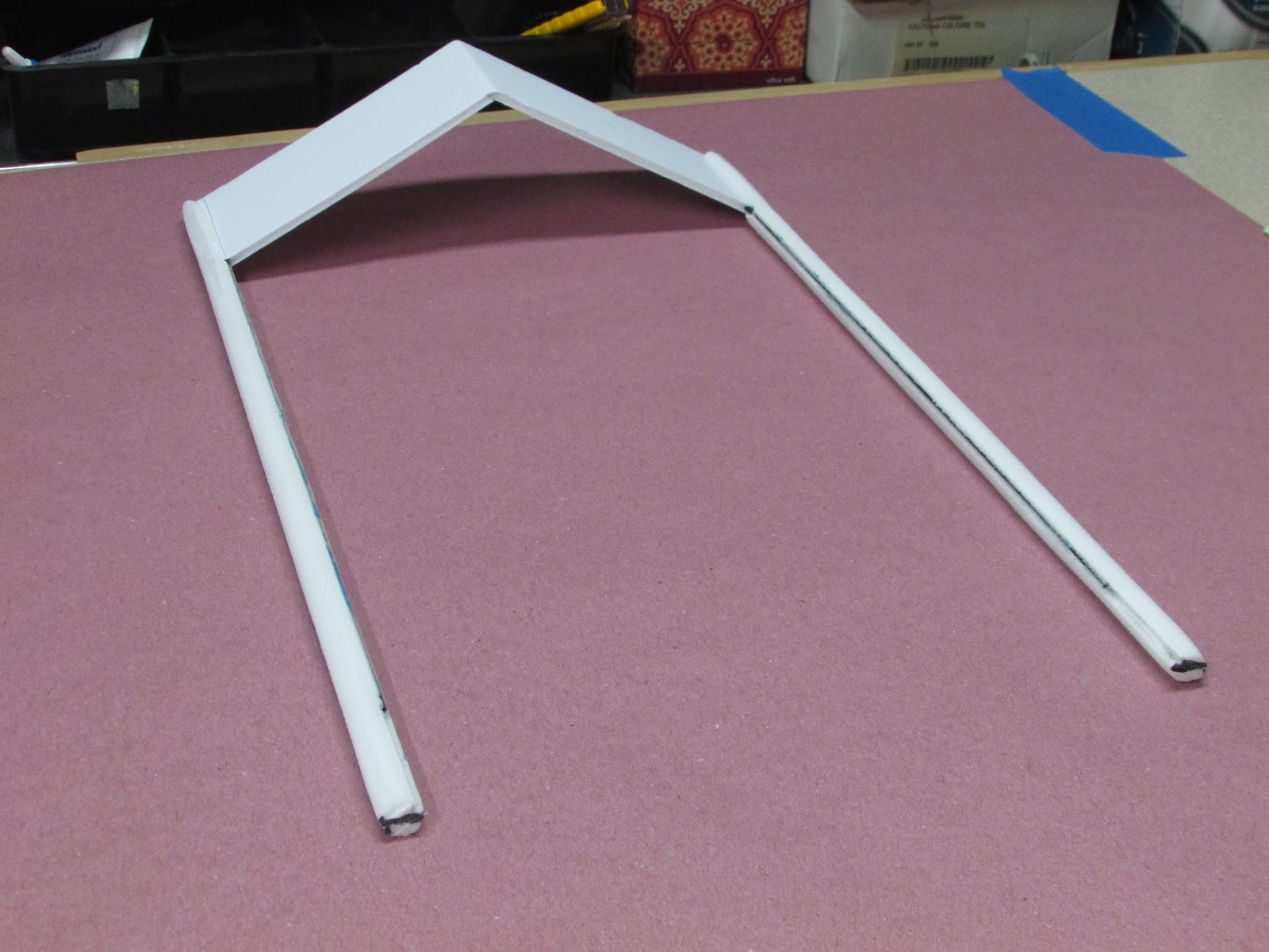
The inverted “V” tails needs some support too. I made an inverted “V” frame from some 2mm or 3mm carbon rod and attached them to each other with epoxy and some fiberglass thread.

After it cured, I sanded the glue joint and glued it into place on the leading edge of the tail. With the tail affixed, it is time to prepare the front of the booms to attach to the wings.

The forward end of the boom has to be trimmed so that the bottom portion fits underneath the wing.

I lay the tail section flat on the table and then cut parallel to the table. The piece can be sanded if the cutting wasn’t perfect.

The final wing/boom connection should look like this above.

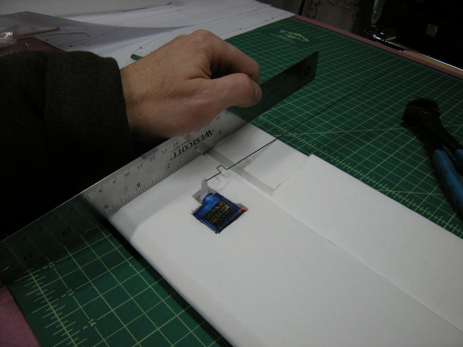
The inside of the boom needs to be trimmed so the servo control arm has a place to go. Here is a photo of the prototype wing and broken servo I used to make sure the control rod could be fed into the carbon fiber tube after the wing the boom is joined to the wing.

Here is how the tail servo is placed before the boom is attached. The servo arm needs to be trimmed by about 2mm so the servo can lay flat on the bottom wing panel. I feed the pushrod through the fourth from the axis hole.
The aileron servos are secured into the wing in much the same way. The major difference is that the aileron servos will be glued to the inside of the top wing surface directly to the rear of the spar. The servo will sit at an angle as determined by the slope of the wing airfoil. The servo will need a 15cm servo lead extension to get the wire to the middle of the wing.
Cut out the servo hole, trim the edges of the hole to match your servo.

Feed the servo wires to the middle of the wing and glue the servo in place.
When the servo is set, align the aileron trailing edge to the bottom edge of the wing and attach the control rod to the aileron surface.
Making the Fuselage.
Cut out the fuselage pieces.
This box fuselage uses the standard Flite Test technique.

Glue the bottom panel nose to the fuselage sides. Make sure the top panel fits, but do not glue it. Before attaching the wings, the back of the fuselage box shape must be completed. I cut the back off the top panel of the fuselage and glued it in place to give the box added strength for mounting the wing. The rest of the top panel of the fuselage can wait till the end or be left as a hatch. I like the idea of having a completely open fuselage to add FPV gear and the like.

I add a form fitted piece of plywood to the nose of the fuselage bottom panel to which the front landing gear will be secured. Glue it in place. I punch a couple of holes through to mark its placement so that when mounting the landing gear I know where to cut my attachment points.
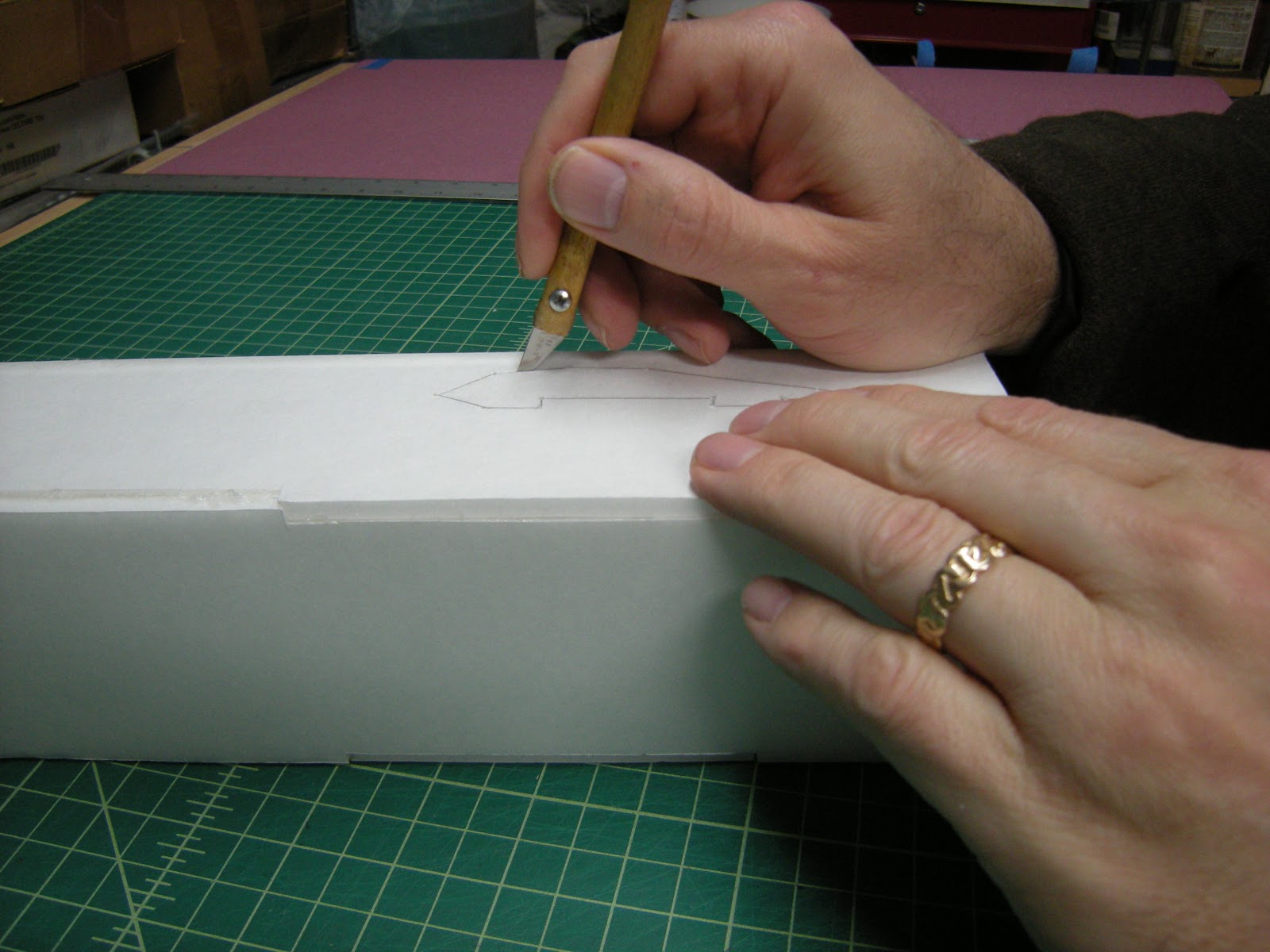
Cut out the wing slots by following the dot-to-dot trace.

To fit the wing into the slot, the top fuselage panel needs to be lifted.

Cut the side panels above the wing as shown above and bend up. Use a straightedge to crease across the top of the fuselage and make a small cut in the side of the fuselage from the top of the wing slot to the top surface of the fuselage to make a hinge,
Mounting the Motor to the wing.
The benefits of mounting the motor to the wing is that I think it is the easiest. Secondly, in the event of a crash where only the nose is damaged - no problem, just cut out another fuselage and attach it to the wing, the fuselage is completely independent of the wing booms, electronics and is replaceable (see end of article for example of a crash). Furthermore, if you need a longer fuselage, just make another one and cut it longer.
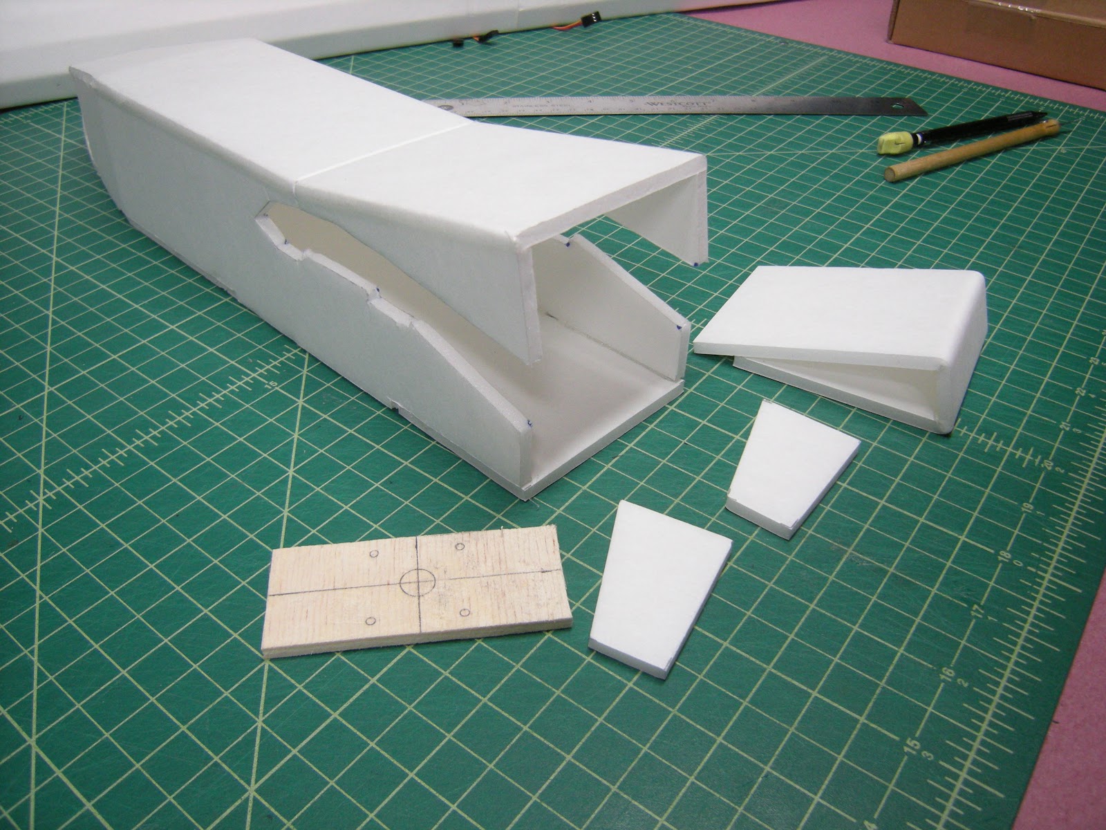
The wing motor mount assembly is created from 4 parts shown above, the fuselage, a folded foam core triangle motor mount, a small piece of plywood and two wing support pieces.

For the plywood I use is a leftover piece of flooring underlayment. It needs to be big enough to attach the motor and fit to the folded motor mount piece.
Cut out the motor mount piece and crease along the fold lines with a straight edge.

Bend the foam core at the crease lines to form a triangle with the one end meeting the line.

Apply hot glue to the creases and along the inside of the marked line where the end will meet.

Fold and hold it together until the glue solidifies.

Slide the motor mount into the fuselage to ensure that it fits neatly and the back surface is parallel to the rear of the fuselage as shown above.

Glue the wing support pieces along the side panels aligning the underside of the wing cutouts with the supports.

Slide the wing into place by opening the wing slot. The wing should slip into the slot and the tabs engage the slots in the wing.

The wing should sandwich nicely between the top of the fuselage and the bottom and the folded motor mount should fit snugly between the top of the fuselage and the wing.

With the motor mount foam in the fuselage, glue the plywood to the motor mount foam.

With the wing fully engaged in the fuselage, apply a nice layer of hot glue (or other) to the bottom (the side that contacts the wing) and slide it back into place. When the glue has solidified, the top of the fuselage can be lifted and the wing removed.

The fuselage can be completely separated from the motor mount and wing. The benefit here is if you auger the nose into the ground, you can replace it.

Bamboo skewers are fed through the holes to hold all the parts together. A rubber band will be used to hold this together.

Mount the motor to the plywood and run wires under the wing to the ESC attached to the bottom of the wing. Attach the servo leads and ESC to the Rx. Attach the Rx to the bottom side next to the ESC and make sure the battery lead pointing forward.
Landing Gear
To attach the rear landing gear, a piece of plywood needs to be attached to the rear of the fuselage.

I’ve included the pattern of the music wire for the landing gear on the plan. I practice bending coat hanger wire until I get the shape I want and then I use the music wire for the actual landing gear. I took me a few tries to get it right, as you can see.
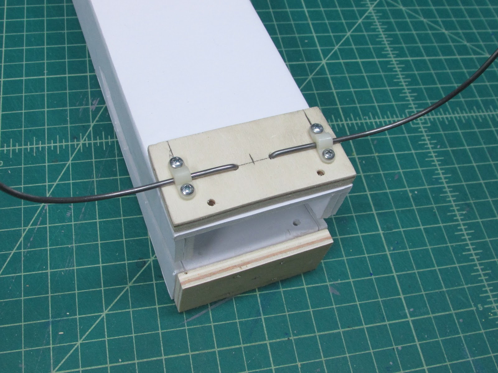
The music wire is attached to the plane in the most simple way I know. The wire has an “L” bend on the end that is fed into a hole. This type of two point attachment prevents movement in any direction. In other prototypes I have used zip ties in place of the brackets, but it was a little too loose for my liking. The rear landing gear is 16 cm long. Bend to the plan and attach.
The wing sandwich will be held closed with a couple of skewers and a rubber band. The skewers are run from the top of the fuselage to the bottom, so to traverse this I drilled a couple of ⅛ inch holes in the landing gear plywood .Glue the plywood to the bottom side of the fuselage. Poke a hole from the bottom to the top with a skewer passing through motor mount and the holes in the plywood.
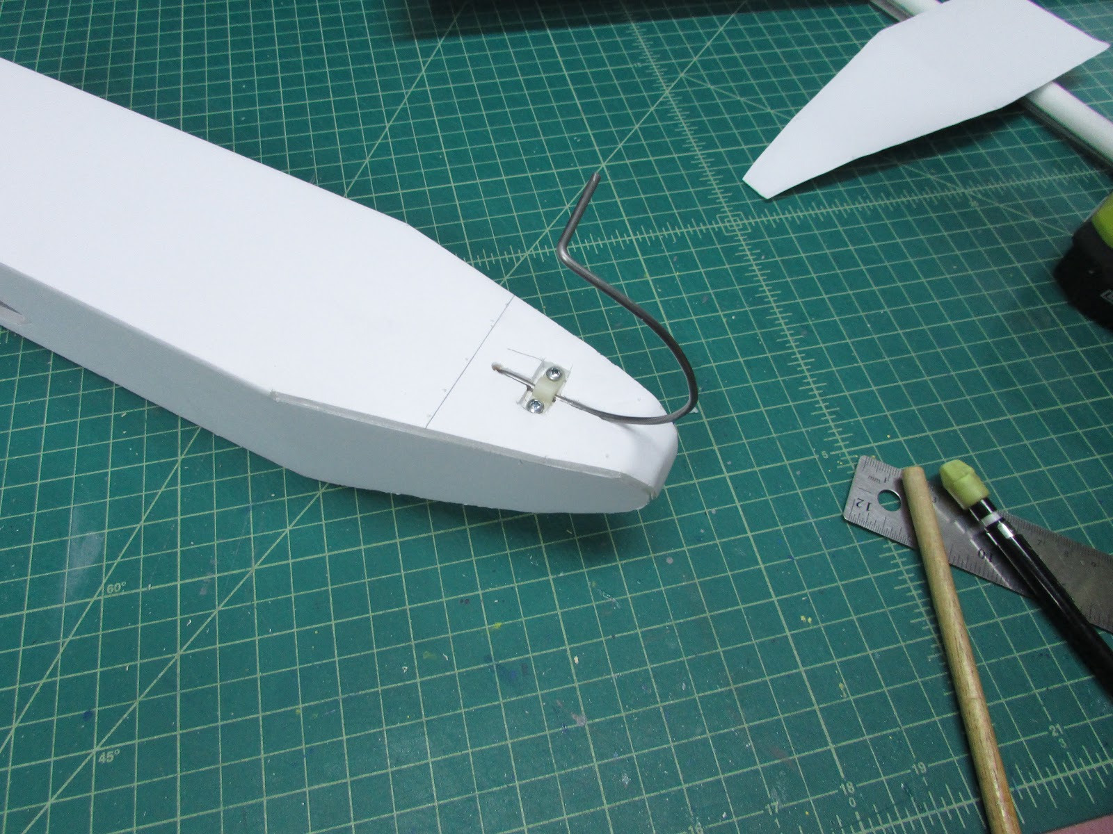
The front landing gear is secured by cutting out a slot for the wire and bracket. Screw it into the plywood that is mounted on the inside. The front gear is made with a piece of steel rod that is 17 cm long.
Battery Cradle
There are more than 101 ways to secure a battery in the plane. I offer one suggestion. I like using a cradle.

To do this, just build a small foam core box for your battery. I measure the battery and add 4mm for every bend, so if the battery is 3.5 cm long, you will need the foam folded at locations 4.3 cm apart. Fold and glue the cradle together.

Put the battery in the cradle and place it into the fuselage and balance the plane by moving the battery inside the fuselage. The CG is on the wing spar.
Paint

The paint is 9 parts white and 1 part black acrylic art paint. Then I dilute 50:50 in water and painted with a brush. The grey was overlaid with DuraClear polyurethane gloss varnish.

Couple of little decorations for the belly carved out of foam.
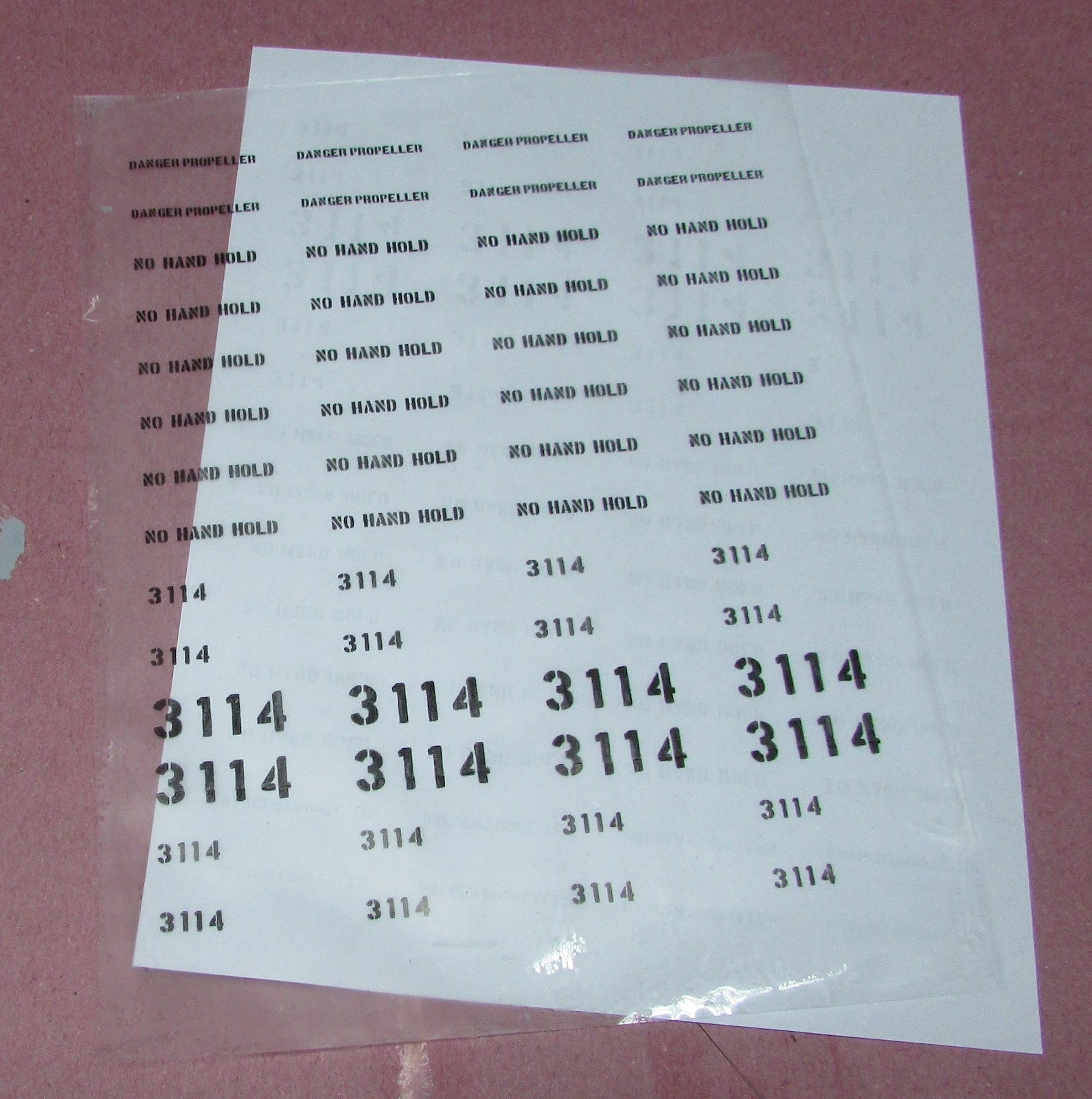
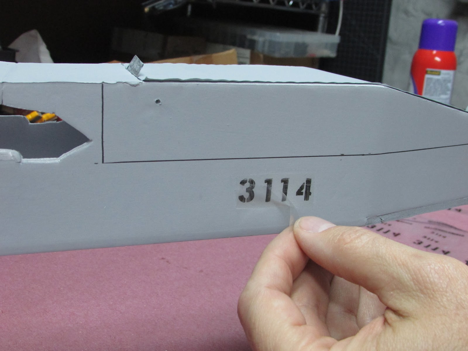
I made some decals to give the model that finished look…
Bet you thought that was my model.. psych!


Triumphant after the maiden.
Looks pretty cool.
Appendix - Versions of the RQ-7 Shadow
Three complete versions of the aircraft were made.

Making a new design takes me a few tries. Here is a photo of v1 (front right fuselage) and v2 (left fuselage and front wing). V1’s electronics were cannibalized to produce V3 (rear wing). If you want to read about the v1 build, it is in the FT Forum.
RQ-7 Version 1 Materials
- Foam Core - 2 sheets of Readi-board (Dollar Tree)
- Carbon Fiber Tube - 2 pieces of 3 mm (Radical RC)
- Servos, 6x 9g servo (Hobby King)
- Servo wire extensions - 2x 15 cm. DIY or Radical RC
- Coat Hanger for landing gear and foam wheels.
- Plywood - USA Balsa, home building center, etc.
- Bamboo skewers (Walmart)
- Control horns (Hobby King)
- Motor - D2628 2200 Kv or similar (Hobby King)
- Propeller - APC 6x4 (Radical RC)
- ESC - 30 Amp ESC (Hobby King)
- Battery - 2200 mAh 3S 40C LiPo
- Receiver - OrangeRX 615R
Version 1 had deployable flaps that were not duplicated on V2 or V3 because I thought the weight and difficulty penalty was too high. Maybe I’ll add them back if I do a bigger one - I’d like to get the wings to about 60”.
Here it is… CRASHED booms tore off.
My analysis - looks like it wants to roll left. Don’t know if the ailerons were out of alignment or the flaps. Doesn’t matter at this point… V1 doesn’t exist anymore.
RQ-7 Version 2 Materials
Same as above except-
- Removed flaps so only needed 4 servos.
- Added another carbon tube to the tail boom so you’ll need 4 pieces of 3 mm carbon fiber tube. The carbon fiber was added to the top of the tail booms because version one was a little flimsy for my liking and broke on maiden crash.
- Added carbon fiber to leading edge of inverted “V” tail.
RQ-7 Version 3 Materials
Same as version 2 except
- Used Ross foam core (Walmart)
- Used 2 mm carbon fiber rods. I liked the stiffness of the 3mm carbon fiber tube in V2 better.
- Reduced battery size to 1300 mAh 3S 40C LiPo. I changed this before I saw version 2 fly. I was concerned that the wing loading was too high, and after seeing the v1 crash, I wanted it to float. V2 seemed to float just fine, but at that time I had already made space for the smaller battery. Can always go bigger.
- Receiver was changed to FrSky V8FR-II HV with long antenna fed into the wing’s leading edge. I thought this was the failure of V2 - lost connection due to the placement of receiver and battery, ESC, Motor et.
- Used heavier duty steel music wire for landing gear rods 3/32 (2.4 mm) piano wire (Radical RC). On V1 and V2 I used coat hanger wire for landing gear. It is not tough enough. It works great to mock up a design, but it lacks the strength for a landing
- Battery hatch was expanded to be top panel of fuselage forward of the wing. Allows for battery placement.
- Version 3 is much more “scale” because I took the time to make the booms three play and round them.
- Version 3 has redesigned the tail and how it mounts to the booms and also how the boom attaches to the wing.
Friendly onlookers.
HilldaFlyer, April 2016
Appendix - Alternate ways to mount motor
Mounting the Motor to the Fuselage - Previous versions had the motor mounted to the fuselage instead of the wing. To mount the motor to the fuselage, you will need to get a 90 degree mounting bracket of some sort.

There are many designs, but here are the three that I use: aluminum plate bent to 90 degrees, Homemade FT elements motor mount, and 1/16 inch aluminum stock angle.
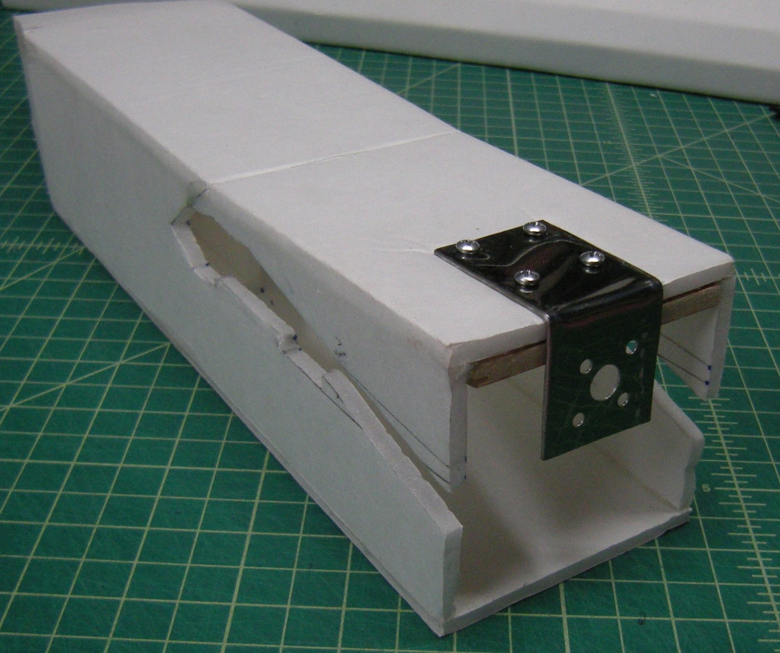
You can use these to mount the motor on either the top or bottom fuselage panels.

When securing these to foam, I usually glue and screw through the foam to a piece of plywood mounted on the other side of the fuselage.
Top...

Or bottom...
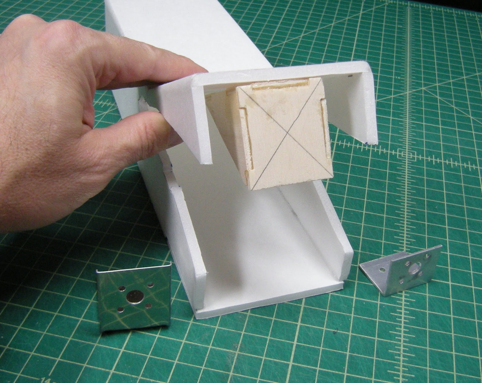
When using FT elements motor mount, you will need to cut away a portion of the wing to make room for the motor mount.
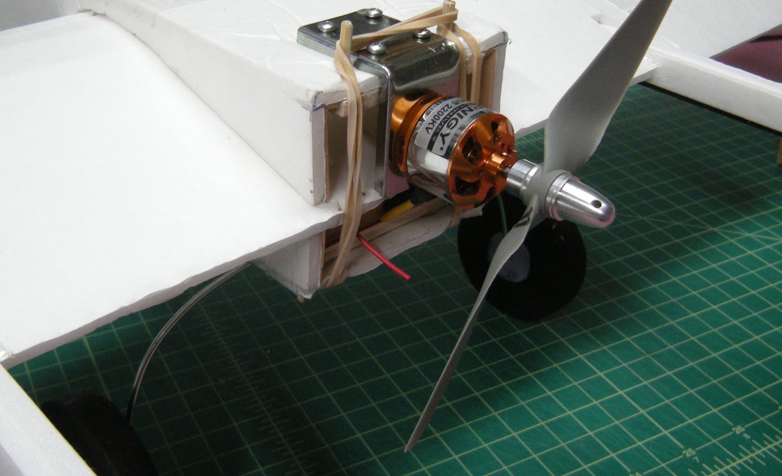
The side walls of the rear fuselage will need to be reinforced so that when it is held closed with a rubber band, the fuselage will stay square. The skewers in this setup only went to the plywood on the top and bottom surface. Next time I’ll run it completely through from top to bottom for added structural strength like the previous mounting to the wing. If you look closely to can see that I mounted tongue depressor to the side walls to reinforce the foam board.
Appendix -Crash and Repair
The RQ-7 Shadow v2 maiden on April 9, 2016. I had to add in a lot of down trim to get it to fly level but once trimmed, it flew really well. Frankly, I was surprised that it flew so well considering the 2200 mAh battery. While setting up the approach for landing, the plane spiralled out of control and nose planted.


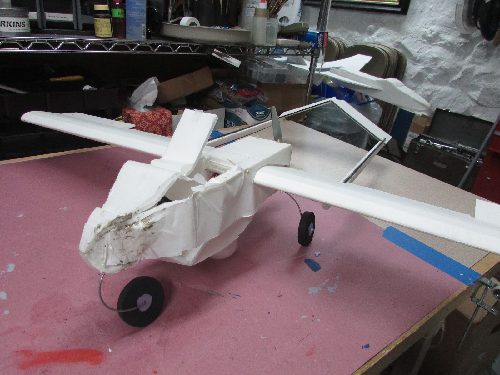
Here is a photo of the RQ-7v2 after the crash. This is why I really like the wing-mounted motor. Pull off the rubber band, slide the skewers out and the crashed fuselage comes off of the undamaged wings.
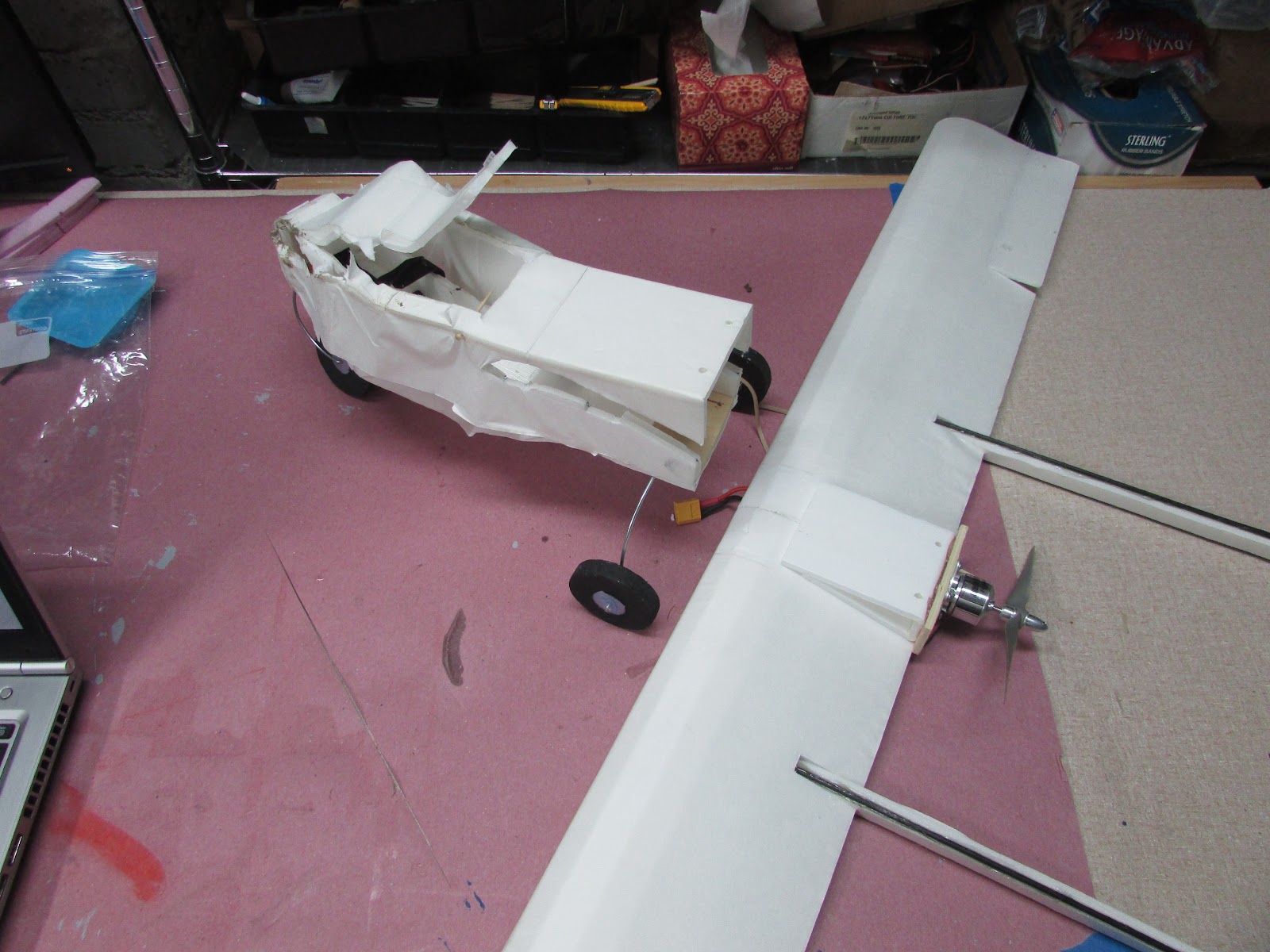
Photo showing the separation of the fuselage from the undamaged wing.
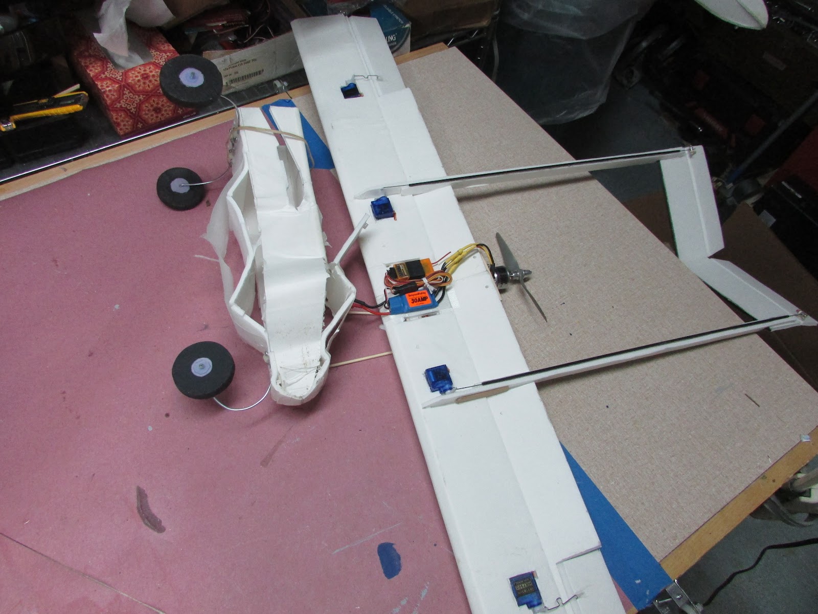
Photo showing the underside of the wing. See how close the receiver is to the ESC. It is also setting right behind the battery. Verson 3 I used a FrSky receiver with long antennas fed down the leading edge of the wing. A new fuselage can be made in less than an hour (with hot glue).


Log In to reply
Log In to reply
Log In to reply
Log In to reply
Log In to reply
Log In to reply
Keep having fun!
Log In to reply
Log In to reply
In the forum several people had great suggestions for the boom. For the booms to be "scale" they needed to have a 1.3cm diameter. Materials like a single carbon fiber or fiberglass tube of that size would have been pretty heavy, so I opted for foam reinforced with carbon fiber. If you're not building to scale, the a smaller tube would probably work fine and be much easier to build. Maybe next time.
Log In to reply
Log In to reply
Log In to reply
Log In to reply
When looking into the RQ-7 Shadow, I ran into its predecessor, the RQ-2 Pioneer, same body and booms but the RQ-2 has a flat horizontal stabilizer between the booms rather than an inverted "V". The RQ-2 would have been much easier to build with the 90 degree angles on the tail... but I wanted to see how the inverted "V" tail worked. To be more accessible to FliteTest easy build - the RQ-2 Pioneer is a better choice.
Log In to reply
Log In to reply
Log In to reply
Log In to reply
Log In to reply
http://forum.flitetest.com/showthread.php?22557-Scale-Build-Off-%96-RQ-7-Shadow
Best of luck and let me know how it goes. I thought it flew really great.
Log In to reply
Log In to reply