Found plenty of designs for mini quads that I liked. Couldn't find one for a mini tri. Took a crack at my own design, pretty happy with the results.
Took the prop speed of a Blackout, the coreflute Whaka body, a bulletproof 4S power system and a rotating tail design I've been thinking about for a while and built a 310mm airframe dubbed the Tri-Hard.
Nimble on 3S, Screams on 4S... Built for speed, more speed, agility, and taking the inevitable pounding. Enjoy!
Many thanks to Blackout for showing just how well a mini-multi rotor could fly, your videos inspired me to scale things down solving problems I had with the tail.
And thanks to Whakahere for the coreflute body concept. The ESC's, power distribution, general wiring and tail servo are all protected inside the "clamshell" coreflute body. Flight Controller and Receiver on top and the battery on the bottom.
Components used:-
Components used are all commonly available. No more waiting for SunnySky motors.
Motors: CF2212 1534KV
Props: 6x4.5 3 bladed plastic held on with zip ties
ESCs: SimonK flashed HK F30A
Tail Servo: Turnigy 380MAX Metal Gear
Controller: KK2.0 with 1.6a Steveis modded firmware
Receiver: FrSky D4R-II with telemetry
Transmitter: FrSky Taranis
Battery: 1800mah 4S 40C Zippy for speed runs or 2200mah 3S 25C Zippy for general flying.
Flying Weight: 450g without battery or FPV gear.
Flight time: 9.5 minutes gentle flying on a 2200 4S including FPV gear, 4-6 minutes aggressive flying on a 1800 4S no FPV gear. 7-8 minutes on a 2200 3S for general FPV and backyard flying.
I flew with a 4500mah 3S once for a dare and surprisingly if flew around the backyard fine. I don't know what the limits are yet, but it's able to carry extra weight.
Top View:-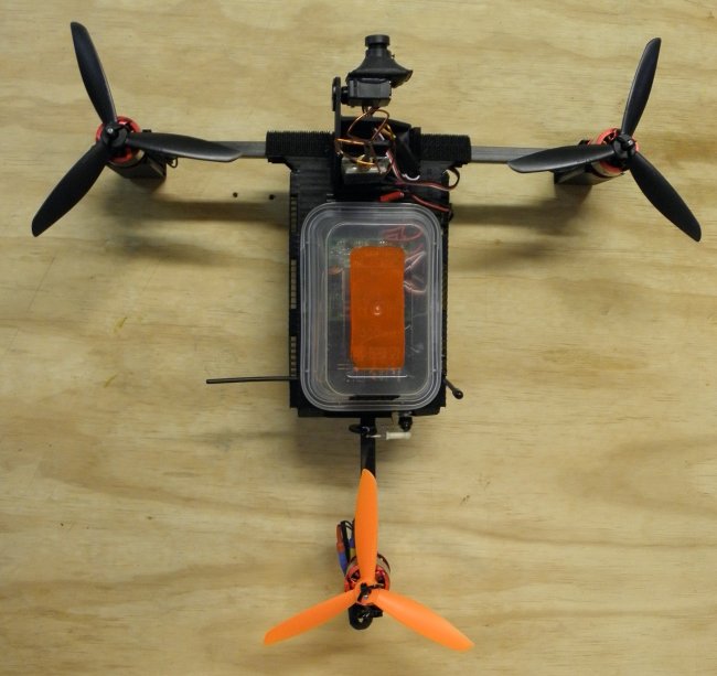
Download Plans:-
Tri-Hard Layout and Template Scanned PDF, please print to scale. Grid is 5mm. (approx 5 lines to the inch)
Build Summary:-
This is not a 2 minute build, but none of the steps are rocket science. Took me about 8 hours to build, I was designing as I went and I am not a fast builder. This article contains a build summary that experienced builders should be able to follow. There will be another article with more detailed build instructions for those less experienced with the materials and skills required.
Apart from the electronics listed above, you will need:-
1 x 10mm Square CF Tube 750mm - Cut 1 x 340mm (front arm assembly), 1 x 120mm (tail pivot), 1 x 70mm (tail mount).
1 x 8mm Round CF Tube 750mm - Cut 1 x 215mm (tail tube), 2 x 30mm (front arm reinforcers).
Approx 500mm x 140mm of 5mm coreflute. I cut a 140mm strip from a large sheet first, it's then easy to work with. After cutting the body, you will need the left over end to cut the legs so cut the body out close to one end.
Legs are 30mm x 140mm strips for the front and 20mm x 140mm for the back. Folded over to make "V" shaped legs at the front and a double thickness single leg at the rear.
Auto Body Tape. This is REALLY sticky weatherproof tape used to stick body trim onto cars. I bought mine at a local auto store. Handy stuff.
50mm wide super strong velcro. I put a strip along the entire bottom then around and over the front. Who knows what I will want to stick on this thing at any given moment!
Most of the other stuff, experienced builders are likely to have, like CA, epoxy, heat shrink, general tools etc. I do not cover specifics on how to wire things up here, but provide general build instructions that someone who has built a multirotor before can follow.
The basic process is:-
- Cut all carbon fibre lengths required. (lengths above)
- Drill holes in the front arm assembly so motor wires can feed from ESC's in the body out to the motors.
- Epoxy the tail tube into the tail mount so that the ends are flush. Epoxy the 30mm inserts in the ends of the front arm assembly so the are flush also.
- Cut the Coreflute body shell using the reversable template provided above. The body is one piece, you mark one end using pins through the cormer holes, then mark the other end by turning the template around. Use the common "Front" section for alignment. You only cut the flaps (shaded) on one end.

- Flame plasma treat all inner surfaces on the Coreflute where you need to glue or apply adhesive. (IMPORTANT - glue will not stick to Coreflute unless you do this. Sounds scary, but this is as close as it gets to rocket science... Just run a blue flame at a steady pace over the coreflute surfaces you need to glue. Will do a video on this. A little practice, and it becomes easy.)
- Stick all arms to the bottom of the coreflute body shell using double sided auto body tape. (used to stick badges and trim on cars. VERY sticky stuff.) Apply auto body tape to the top of the arms as well but DO NOT STICK THE TOP DOWN. Leave the cover on the tape for now.
- Wire the ESC's together with the power feed wires hanging out the bottom of the body (make a hole), the esc output wires through the middle of the arms, and the control wires up through the deck.
- Glue the tail servo into the body using CA.
- Cut the coreflute legs, 2 for the front, one for the back plus a coreflute retainer for the tail assembly.
- Attach the front legs and the motor bases using zip ties and auto body tape under the motor bases.
- Slide the tail pivot on the tail, glue the retainer in using CA and kicker.

- Glue the rear leg on behind the retainer with CA, attach the rear motor base to the rear of the tail pivot.
- Make the tail pivot arm and glue it on near the servo. Make a connecting rod and attach the tail pivot arm to the servo arm.
- Solder female bullet connectors on the wires poking out the end of the arms. Solder male bullet connectors on the motors. Add heatshrink as required.
- Mount and plug in your motors temporarily, then use a servo tester or your receiver to test all 3 esc's and the tail servo. Center the tail servo while you are there.
- Poke the control wires out through the hole to the top. Stick the top of the coreflute body shell down onto the arms using auto body tape, and to the tail servo using CA.
- The body should be pretty solid now. Flame plasma treat the top and bottom everywhere you want to stick anything, then use electrical tape bands across and around the clamshell body to give it strength.
- From this point you stick some velcro across the bottom to mount your battery, and around the front if you want a camera mount, then mount your flight controller and receiver on the top.
- Stick on some props using zip ties (or collets if you like bling and don't mind the weight), setup your flight controller and give it a quick maiden.

- Once you are happy with basic flight, stick your favourite food container on top to protect your flight controller and receiver. You've seen the result with container up the top, here's another view in case you want a close up of the front for reference.

The food container is more important than you might think... I had problems with unstable flight at high speed until I put a cover over my flight controller. Apparently the wind buffeting the KK2.0 board was upsetting it's sensors. I added the 300ml takeaway container and it's been solid as a rock since then.
There's nothing underneath to see but an XT-60 hanging out. That's it for now, get out there and build one!


Log In to reply
Log In to reply
Tail is made up of a fixed round hollow shaft with a piece of 10mm square CF on the outside. The hole in the center of the square CF is round, so is fits on the shaft and rotates easily. The servo rotates the square CF from the body of the craft, and the motor is mounted on the square CF at the rear of the arm. In operation it looks like the whole rear arm pivots but it's only the outer square CF tube rotating. There is also a retainer on the end holding the square CF on the shaft.
Thanks for your question, hope this helps. If you have more questions, please post; will reply then add to the article as we go. And maybe do a build vid. :-)
Log In to reply
Log In to reply