Supersized FT-22 - 150% times BIGGER than the original.
Constructed with fiberglass skinned foam core.

For the 400th episode of FliteTest, Josh and Dave built a Cruiser and Spitfire at 200% and they flew great. Lots of laughter and good times.
The FT-22 is a really easy plane to build and flies incredibly well for a plane that is supposed to be inherently unstable. I’ve had a ton of fun with first 4 I’ve built. I’ve even had a couple of kids over to build them in a few hours with great results. Me being me, I wanted a bigger version, but the challenge is to build the wings strong enough - I doubted that Ready-Board alone would have the structural integrity to deal with the forces of flight.
Super Strong foam core can be made by removing the paper and adding a fiberglass skin (http://flitetest.com/articles/super-strong-waterproof-foam-core). I have used this technique to successfully built regular sized FT-22 (http://flitetest.com/articles/glassed-ft-22) and versa wing (http://flitetest.com/articles/balanced-pusher-wing).
Peter was known as the foam and tape guy, so I imagine it is only a matter of time before I get called the foam and fiberglass guy. The only way to truly know if fiberglass foam core is strong enough for a scaled up model is to try. If it isn’t strong enough, I will end up embedding carbon fiber rods in the wing panels like Dave Powers does with his Depron designs. If you don’t want to get into fiberglassing, I’ll bet you can keep the paper and reinforce the wings and other parts with carbon fiber tubes.
SPOILER ALERT - IT FLIES!
Maiden flight analysis.
Stable from the start - I was really excited that it flew so well on the maiden. It didn’t take much trim during the first flight. If you listened to my ramblings on the maiden video, you will hear keywords like, ultimate slow flier, severely underpowered, slow - meaning very unresponsive to roll control input (the elevator response was great). But at time I maidened this, I had just got done flying my Balanced Pusher Wing at screaming hot speeds. I suggested that a plane this size needs ailerons to help with the snap rolls, that is, if you really want to snap it over. Otherwise, you see what you get, a slow roll that is stunning, adequate speed at level flight, pretty average climb rate and a plane big enough to see across the field.
Power and Speed - The powertrain (specifications at the end of the article) produces almost a 1:1 thrust to weight ratio, so it flies great but does not go vertical for long. In the maiden flight, I demonstrated a vertical climb, but I didn’t have the throttle pegged, so I will have to try a long vertical climb later. All in all, I was awesomely pleased with the flight. It is a very easy and docile plane to fly and tracks like it is on rails. I was really impressed with the stable level flight and landing/stall characteristics. Static thrust data indicates that the motor reaches about 7500 RPM at full throttle. With the 9x6 propeller, and disregarding inefficiencies, blade slip and plane drag etc., I calculated that the plane will theoretically reach 40 MPH. Watching it whizz by, I bet 35 MPH is the ceiling. Still - it looks way super cool.
Launching - Before completing the prototype, I was a little worried about the wing withstanding the stress of a one-handed launch. After it was built I had little doubt it would work - hold it by one wing, give it some throttle (75%) and toss it into the air. This concern was completely eliminated on the maiden flight. It practically flew out of my hand.
Enlarging the Plans.
At first I wanted to make the enlargement twice as big (2x) as the original, like Josh and Dave did for the 400th episode, but I settled on 1.5x (printed the FT plans at 150%) so that the largest piece (one wing section) would fit on a single sheet of Readi-Board. One thing I noticed right off the bat was that enlarging the printed plans doesn’t thicken the foam, so all parts of the plan associated with the foam thickness, like score cut width, the tab height and tab slot width, would need to be adjusted back to the un-enlarged size. I used Adobe Illustrator to resize the score cut marks, tabs and tab slots back to 4 mm, to preserve the parts of the plan the rely on the thickness of the foam. To increase the structural integrity of the plane, I added another skid panel behind the prop and permanently attached to one in front of the prop.
Complete plans - Not Tiled
Supersized FT-22 150% plans - HilldaFlyer
Build Outline
- Peel paper from foam.
- Cut out foam parts.
- Bevel the edges that are hinged.
- Add the fiberglass skin to the foam.
- Glue the parts together.

Peel the paper from both sides of the Readi-Board. Go ahead and peel the whole sheet!

Lay the plans on the foam, mark the foam with a pen where the cuts should go. One thing I learned is that pulling the paper off the Readi-Board induces a considerable amount of static electrical charge. The plans stick to the foam like glue, it is amazing.

Here is a photo with the marks transferred to the foam. Cut out all the parts (outline of the part only). Do not cut the score cuts or the holes for the tabs. They will be cut later, after the fiberglass is applied. There is a reason I follow the procedure. If you cut out the tab holes before applying the fiberglass skin, the epoxy resin will collect in the holes. It is just easier to cut a hole in fiberglass foam core that it is to remove excess resin from the holes. Not impossible, just more difficult.

Fiberglass cloth is mildly expensive, so I like to lay out the parts to maximize the surface area. You should leave about a centimeter of distance between the pieces so they don’t get stuck together during the fiberglassing process.

Overlay both sides of the foam with 1.43 oz/yd fiberglass (Thayercraft.com) and 635 Thin Epoxy Resin with Medium hardner (uscomposites.com). When using fiberglass and epoxy resin, use in a well ventilated area and wear personal protection attire (gloves, mask etc).

I have found the easiest way to spread and “squeegee” off excess epoxy is using a playing card. The picture above was taken with a regular-sized FT-22, but you get the idea. Let the epoxy cure overnight and repeat with the other side. You will need to use a flat surface that is covered to prevent sticky mess from getting on your workbench (http://flitetest.com/articles/workbench-cover). Trim excess fiberglass from the foam and sand the edges with a hobby knife and sand the edges to remove the shards. I’ve found it easiest way to trim the excess fiberglass cloth is to use a piece of sandpaper, just a couple of strokes and it peels off.

Join the two main wing pieces together. Align the two pieces and use a bit of masking tape to hold the pieces together, then turn it over.
I used fiberglass for the joint, but I suppose hot glue and tape would work too.
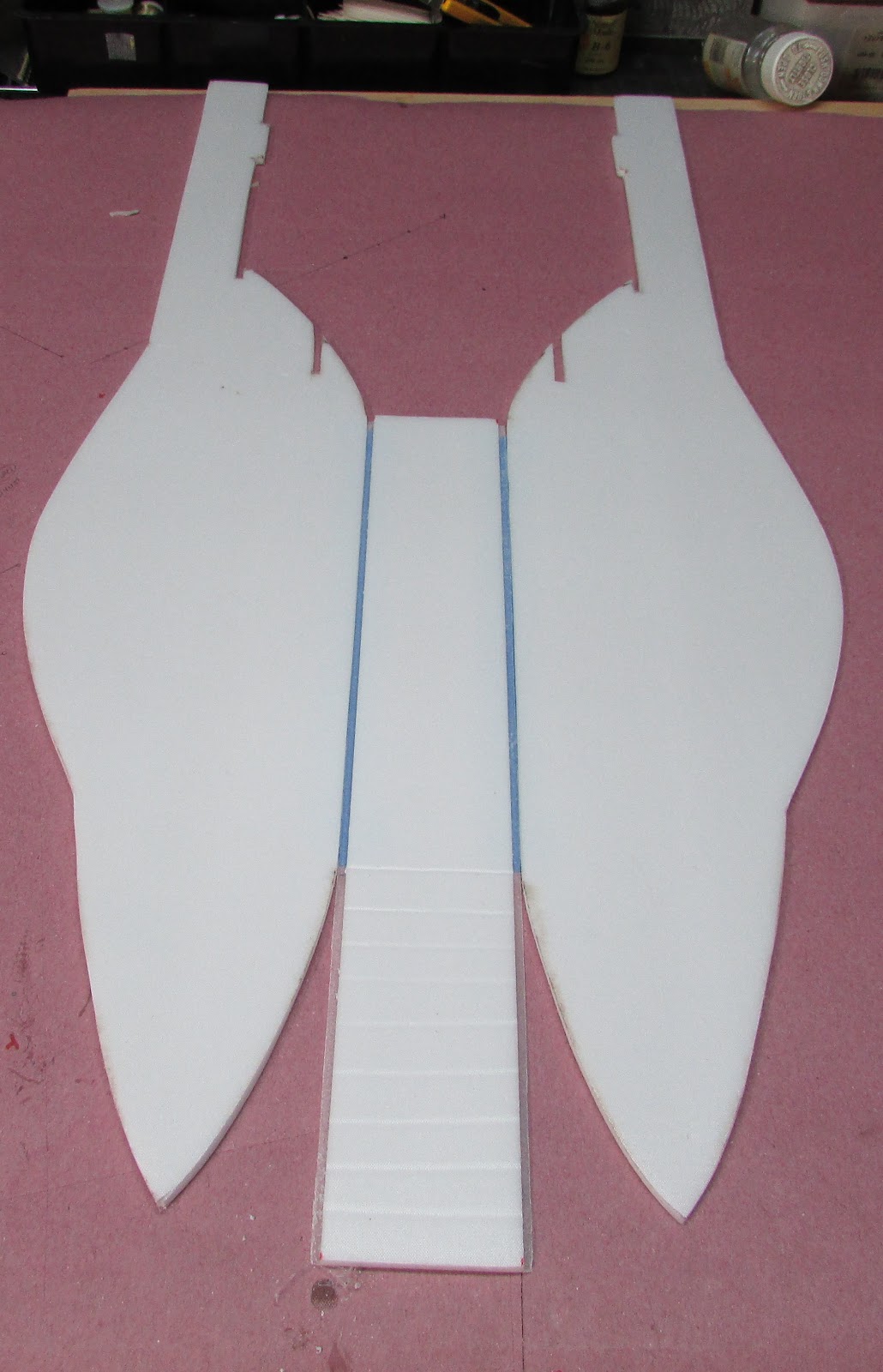
After it is cured, flip it over and repeat. When I fiberglassed the second side of the center seam joint, I lifted one wing tip 5 cm off of the table surface. This added a bit of dihedral and hopefully will contribute a little stability to the flight characteristics.
The fuselage side pieces (engine compartment) can be glued into place on the bottom side of the wing panel.

Fit the pieces into the tabs, run a bead of hot glue under the part and then press it fully into place.

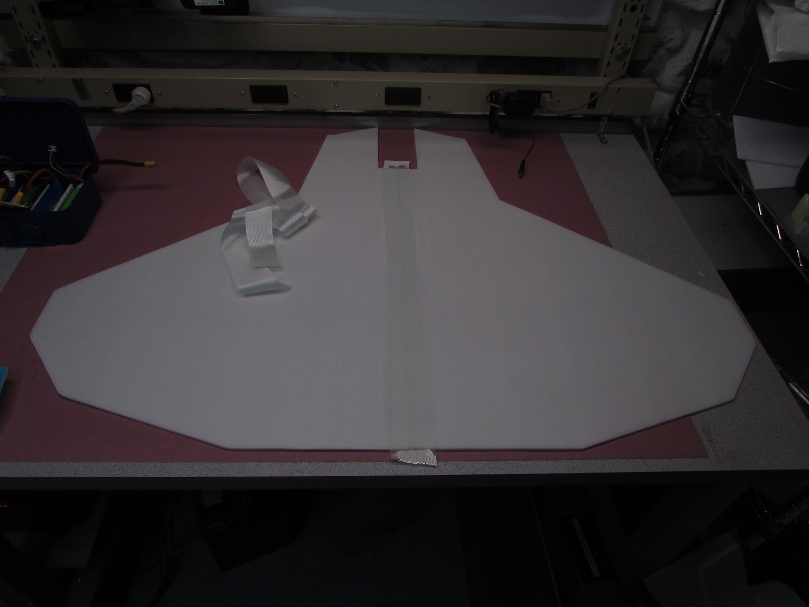
The front of the fuselage panels can be now hot glued to the front of the wing panel. At this point in the build of the prototype, I felt the weakest point of the wing is located along this line where the wing panel meets the fuselage panel. To add strength, I added another fiberglass strip to the top that runs parallel to the center seam. I’ll point it out in another photo later. There is no other structure support added to the plane (no carbon tubes, arrow shafts or wood), just fiberglass-skinned foam.
Make the fuselage. The best trick I know for joining two pieces is to use masking tape to re-create the paper joint or connector that is missing.

Start with your pieces.

Tape the pieces of foam together with a gap the width of the foam, just like the score cut.
The masking tape holds the pieces at the proper distance to form the “A” or “B” joints you are familiar with.

Add hot glue and hold the pieces in place.

Remove the tape.
The top of the fuselage is created by laying a single piece of foam that extends from the nose to rear of the cockpit. This piece has some gradual bends that match the curve of the fuselage and cockpit.

To get this piece to hold its shape, I used a ruler to dent the piece every 2 cm or so to aid in the shallow bend. I ran a smear of hot glue along each of these score marks and held the piece to the desired shape. After doing this, the piece held the shape pretty well.

Glue the long fuselage top cover into place. The way I do this is use masking tape at the front tip as a hinge, add glue and fold it shut.
To the rear of the cockpit is the battery hatch. The hatch is constructed by cutting off the two edges that are score cut in the original FT-22 design.

The cut off edges will be used as jams to hold the hatch in place when closed. To position it properly,

tape the hatch in place, turn the fuselage over and

glue the score cut edges to the inside of the fuselage. To glue the hatch jams in place, I ran a bead of glue along the corner between the fuselage side and the jam and removed excess glue with a piece of foam. Then I turned it over, opened the hatch and used the hot glue bead as a hinge to separate the bumper from the fuselage and I ran another bead of hot glue between the two parts and held them together.
One thing that I added to this plane that is not in the FT plans is a battery tray.

I cut an extra piece of foam the width of the fuselage and glue it inside the fuselage at the same level as the wing slot. Glue the piece into place by running a bead of hot glue along the corners where the pieces meet, both top and bottom.

The hatch can be then joined to the back of the cockpit piece with hinge tape. For hinge tape, I use small strips of polyester cloth and hot glue. I have tried using packing tape, but it doesn’t stick very well to the fiberglass. However, duct tape works great.

Glue the fuselage to the wing. In this photo you can see the extra fiberglass strip running along the line where the fuselage is glued to the wing. It was the same as what I used for gluing the two wing panels together (center seam).

Use hinge tape or your favorite method to join the control surfaces to the back of the wing.

Glue the vertical stabilizers to the wing. At this point the plane is practically done. When I build my next one, I will cut out only the bottom side of the tab holes so that the top surface would have a smoother finish. To do this, just cut through one layer of fiberglass (on the bottom side) and chip out the foam. As pointed out before, in this photo you can see the fiberglass reinforcement I ran along the fuselage/wing joint. I don’t know if this reinforcement is required, but I it adds a support that I thought would be needed.

To get an idea of CG for this prototype, I taped the electronics in the locations I wanted them to go and moved the battery around to balance at the CG.

Everything appeared in order, so I cut the propeller hole in the wing. The motor mount was fabricated from aluminum angle I acquired from a local hardware store. It was attached to a small piece of plywood that was hot glued to the plane as shown. With more beefier motor setups, I would consider adding another piece of plywood below the wing panel and screwing the motor mount to the plane. As it turns out, this worked great for this setup.
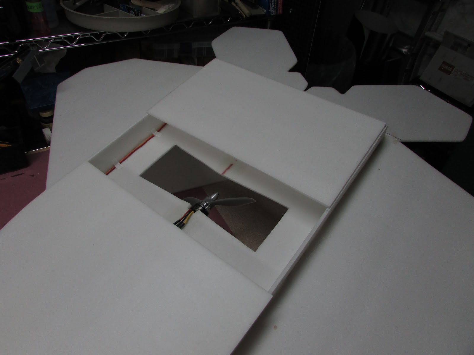
The front skid plate was glued into place. At this point I noticed the the plane was pretty flimsy in the rear where the vertical stabilizers were, so I added a second skid plate from one fuselage side panel to the other behind the prop.
One thing that I didn’t get before I glued it in place was a picture of was the placement of the electronics. Notice there is only one wire running to the back of the plane. This is from the ESC (in the front of the plane’s motor) to the receiver which I located near one of the elevon servos. This put the receiver near the servos so only one extension wire was needed to reach the ESC.
To give you some perspective on how big 1.5x really is, check out these photos.

Normal sized FT-22 sitting on the back of the supersized prototype.

The supersized FT-22 at 1.5x and the Glassed FT-22 at regular size.

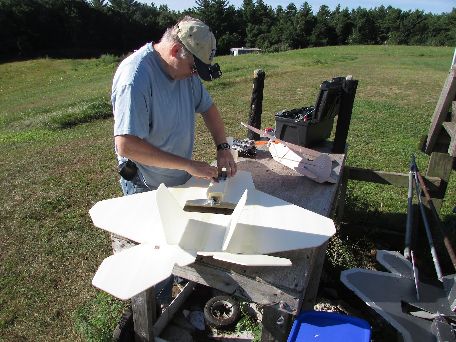
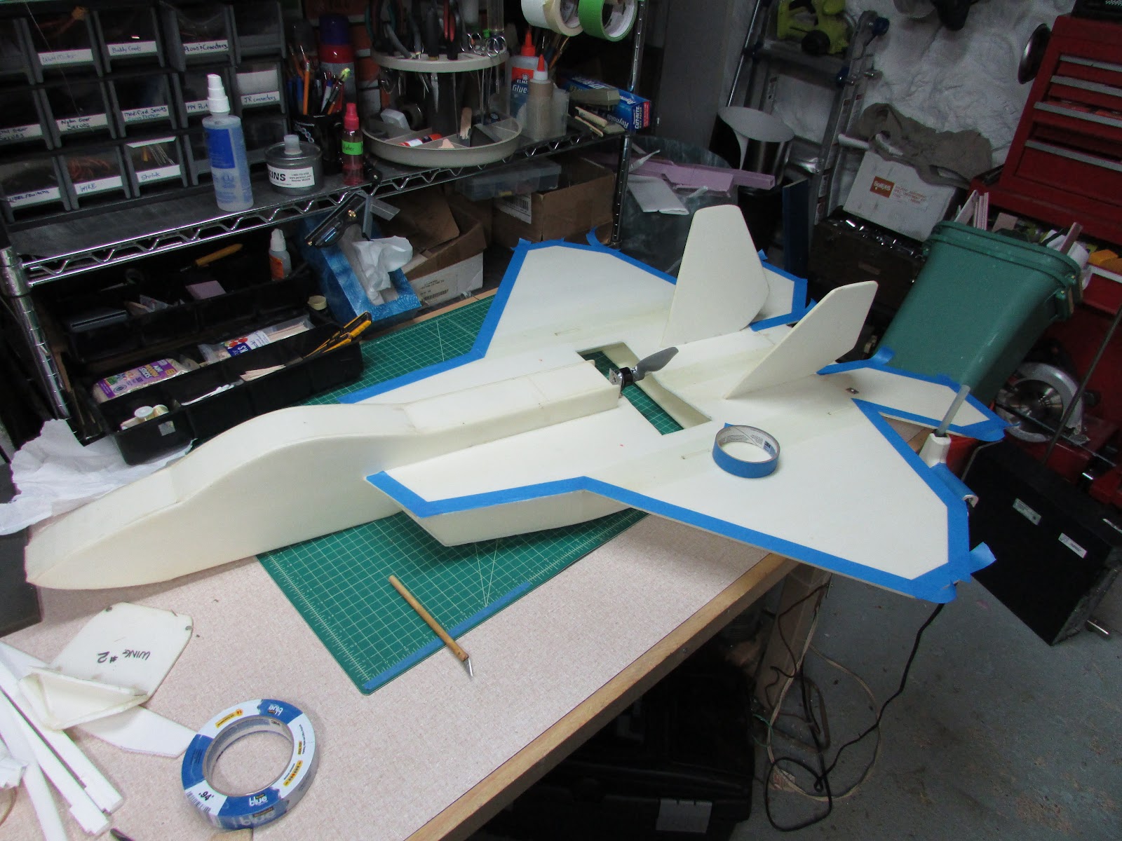
Prepping the supersized FT-22 for the maiden flight.
Maiden Flight
The maiden flight is documented at the top of the article. It flew so well that my nerves and fears were calmed immediately after the launch. It is always good to get a prototype back in one piece.

That was a lot of work… and excitement Time to take a nap.
After the nap, it is time to adorn the plane with more time and effort. In the past I have built beautiful prototypes that just ended up in the trash after the maiden flight. I have now made it a personal policy to maiden the prototypes BEFORE spending more time on adornments - like paint.

For this model, I decided to get out the airbrush and use the same paints as I did for the Glassed FT-22 (in the background). The dark metallic paint is Thundercloud and the light paint for the edges is Polished Silver purchased from Home Depot.
I taped off the parts of the plane I didn’t want dark metallic gray and sprayed. To get the paint thin enough to spray, I diluted it 50/50 with water. Painting with water-based paints like this is possible only if you have removed the paper from the foam (or prepared it to be water tolerant.

A nice warm sunny day in New England provided a fine time to spray.

Wait a few minutes for the paint to dry and peel off the tape. Finish the painting by adding color to the edges and cockpit.
Presto - you’ve got a supersized FT-22.
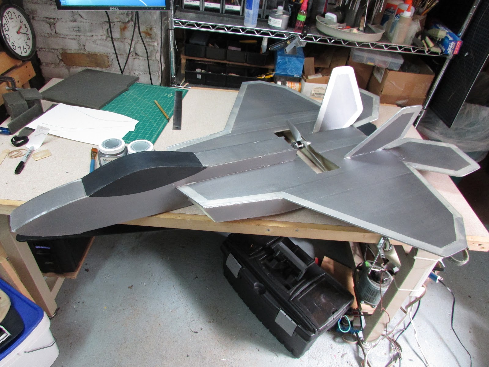
Does it fly any better with the paint? Not really - but it really looks great at the field.
Here are Videos from flight #2 taken from my CapCam (DorkCam) and FPV on-board camera:
More videos from flight #3
Comments - I have to mention that I have been flying in the mornings with dew covered grass. The fiberglass foam core is the best, it is forever! It doesn’t warp or get soggy. Take a peek at these clips.
And... after all that water - the plane is still flying.
I just wish fiberglass foam core was more accessible as a building material so that more people could discover the freedom of using a forever-lasting material - but I have demonstrated that it isn’t that hard to make. It has proven itself to me multiple times and is in my mind, the go-to material for inexpensive long-lasting models. Sure, adding fiberglass to the foam adds a couple of days to the build, but it adds years of life, so long as you don’t crash it!
Materials
- Adams Ready-Board (Dollar Tree)
- Fiberglass cloth - 1.43 oz/yd (http://thayercraft.com/)
- Epoxy Resin - 635 thin (http://www.uscomposites.com/)
- Servos - 9g x2 (Hobbyking)
- Motor - NTM 2826 1200kv (Hobbyking)
- Propeller - APC 9x6 (http://www.radicalrc.com/shop/)
- ESC - Hobbyking 20A (Hobbyking)
- Battery - 2200 mAh 3S 40C
- Receiver - OrangeRx 4 channel DSM2/DSMX
- Transmitter - FrSky Taranis X9D with DIY DSM2/DSMX transmitter module (http://flitetest.com/articles/spektrofy-your-taranis) Elevon mixing was performed by the radio. This function can also be performed with Turnigy V-Tail mixer (http://www.hobbyking.com/hobbyking/store/__6321__TURNIGY_V_Tail_Mixer_Ultra_small.html)
Stats
- Weight of the SS FT-22 without the battery1 lb 6.6 oz (640 g).
- The battery adds 196 g (7 oz) for a flight weight of 1 lb 14 oz or 836 g.
- Wingspan 39” (99 cm)
- Drivetrain produces 740 g static thrust (26 oz) at 16 Amp (177W).
Supersized FT-22 Upgraded - Ailerons and Big Motor
Future Plans-
How about a FT-22 that is 200% bigger than the original. I am so going to do that! But, before I do, my next 1.5x SS FT-22 will have ailerons for a snappier roll, and a beefier power train. I’m thinking that the prop slit is wide enough to support a 10 inch prop, the frame will support a larger battery and motor so my aim is for somewhere around 500 watts, 1400 to 2200 kv on 4S.
Cheers! HilldaFlyer - August 2015


Log In to reply
Log In to reply
Log In to reply
Log In to reply
Log In to reply
Log In to reply
Log In to reply
Log In to reply
Log In to reply